Nissan Sentra. Manual - part 905
TM-256
< REMOVAL AND INSTALLATION >
[CVT: RE0F11A]
CONTROL CABLE
CONTROL CABLE
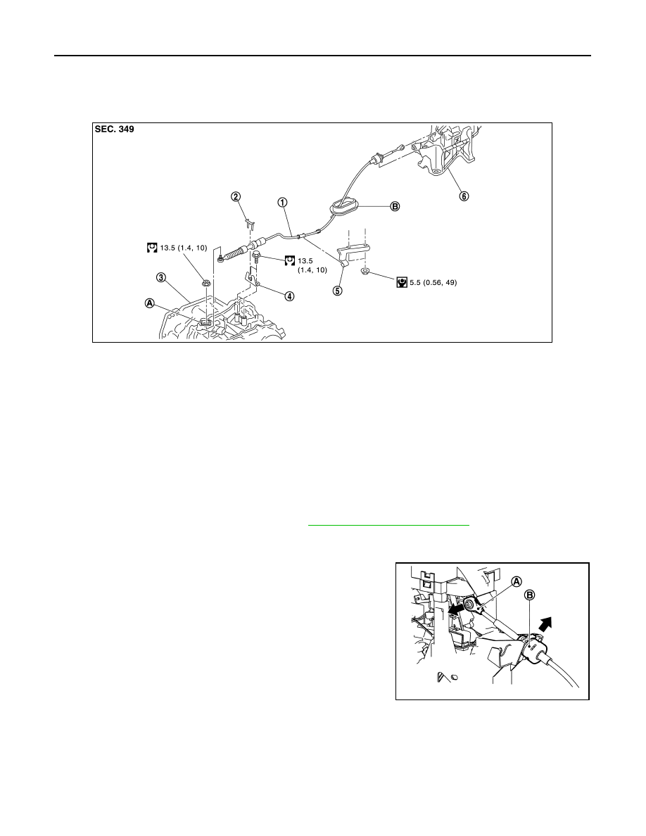
Exploded View
INFOID:0000000009759502
Removal and Installation
INFOID:0000000009759503
INSTALLATION
CAUTION:
Always apply the parking brake before performing removal and installation.
1. Apply the parking brake.
CAUTION:
Make sure the vehicle cannot move with the parking brake applied.
2. Remove the center console assembly. Refer to
IP-17, "Removal and Installation"
3. Move the shift selector to “P” position.
4. Remove the control cable from the shift selector assembly with the following procedure.
a. Disconnect the tip (A) of control cable from the shift selector
assembly.
b. Remove socket (B) from shift selector assembly.
1.
Control cable
2.
Lock plate
3.
Transaxle assembly
4.
Bracket A
5.
Bracket B
6.
CVT shift selector assembly
A. Manual lever
B. Grommet
JSDIA1873GB
JSDIA3655ZZ