Nissan Sentra. Manual - part 904


  Index      Nissan     Nissan Sentra (2014 year) - Service and Repair Manual


Search            


Content   ..  902  903  904  905   ..


Nissan Sentra. Manual - part 904


TM-252

< PERIODIC MAINTENANCE >

[CVT: RE0F11A]

CVT FLUID

• Use only Genuine NISSAN CVT Fluid NS-3. Using transmission fluid other than Genuine NISSAN

CVT Fluid NS-3 will damage the CVT, which is not covered by the (NISSAN new vehicle limited) war-

ranty.

• During adjustment of the CVT fluid level, check CONSULT so that the oil temperature may be main-

tained from 35 to 45

°C (95 to 113°F).

• Use caution when looking into the drain hole as there is a risk of dripping fluid entering the eye.
1. Check that the selector lever is in the “P” position, then completely engage the parking brake.
2. Start the engine.
3. Adjust the CVT fluid temperature to be approximately 40

°C (104°F). 

NOTE:

The CVT fluid is largely affected by temperature. Therefore be sure to use CONSULT and check the

“FLUID TEMP” under “TRANSMISSION” in “Data Monitor” while adjusting.

4. While depressing the brake pedal, shift the selector lever to the entire position from “P” to “L”, and shift it

to the “P” position.

NOTE:

Hold the lever at each position for 5 seconds.

5. Lift up the vehicle.
6. Check that there is no CVT fluid leakage.
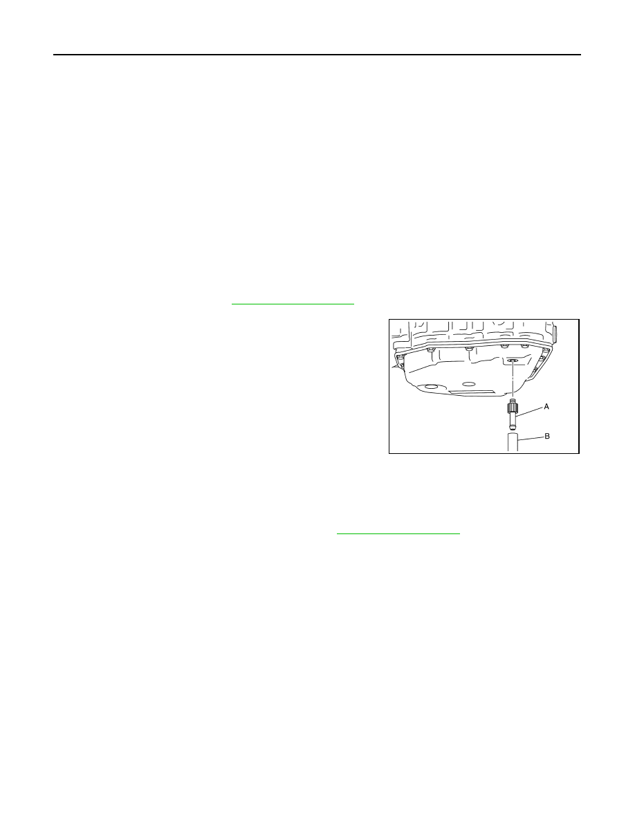
7. Remove the drain plug. Refer to 

TM-266, "Exploded View"

.

8. Install the charging pipe set (KV311039S0) (A) into the drain

plug hole.

CAUTION:

Tighten the charging pipe by hand.

9. Install the ATF changer hose (B) to the charging pipe.

CAUTION:

Press the ATF changer hose all the way onto the charging

pipe until it stops.

10. Fill approximately 0.5 liter (1/2 US qt, 1/2 lmp qt) of the CVT

fluid. 

11. Remove the ATF changer hose from the charging pipe, and

check that the CVT fluid drains out from the charging pipe. If it

does not drain out, perform charging again.

CAUTION:

Perform this work with the vehicle idling.

12. When the flow of CVT fluid slows to a drip, remove the charging pipe from the oil pan. 
13. Tighten the drain plug to the specified torque. Refer to 

TM-266, "Exploded View"

.

CAUTION:

Never reuse drain plug gasket.

14. Lift down the vehicle.
15. Stop the engine.

JSDIA1876ZZ

CVT SHIFT SELECTOR

TM-253

< REMOVAL AND INSTALLATION >

[CVT: RE0F11A]

C

E

F

G

H

I

J

K

L

M

A

B

TM

N

O

P

REMOVAL AND INSTALLATION

CVT SHIFT SELECTOR

Exploded View

INFOID:0000000009759499

Removal and Installation

INFOID:0000000009759500

REMOVAL

1. Turn ignition switch OFF.
2. Move the shift selector to “N” position. 
3. Remove shift selector knob with the following procedure.
a. Slide the knob cover (1) down.

CAUTION:

Do not damage the knob cover.

b. Pull out the lock pin (2).
c. Pull the shift selector knob (3) and knob cover upwards to

remove them.

4. Remove the center console. Refer to 

IP-17, "Removal and

Installation"

.

5. Remove rear floor duct (LH/RH). Refer to 

VTL-8, "Exploded

View"

.

1.

Shift selector knob

2.

Lock pin

3.

Knob cover

4.

Position indication panel

5.

Detent switch

6.

Shift lock unit

7.

Park position switch

8.

Shift selector assembly

9.

Shift selector harness assembly

10.

Position bulb

11.

Key interlock rod

A.

With push-button ignition switch 
system

B.

Without push-button ignition switch 
system

ALDIA0404ZZ

JSDIA3654ZZ

TM-254

< REMOVAL AND INSTALLATION >

[CVT: RE0F11A]

CVT SHIFT SELECTOR

6. Move the shift selector to “P” position. 
7. Remove the key interlock cable from the shift selector assembly. Refer to 

TM-260, "Removal and Installa-

tion"

. (Without push-button ignition switch)

8. Remove the control cable from the shift selector assembly with the following procedure.
a. Disconnect the tip (A) of control cable from the shift selector

assembly.

b. Remove socket (B) from shift selector assembly.
9. Remove harness clips from the shift selector with a clip remover.
10. Remove shift selector nuts.
11. Remove the shift selector assembly from the vehicle. 

INSTALLATION

Installation is in the reverse order of removal.

NOTE:

Pay attention to the following when connecting the control cable to the shift selector assembly.
1. When connecting the control cable (1) to the shift selector

assembly (2), face the grooved surface of the rib (A) up and

insert the control cable until it stops.

2.

Install the socket (A) onto the shift selector assembly.

CAUTION:

• Place the socket onto the shift selector assembly, then

fasten it in place from above.

• Check that the pulling on the socket does not disconnect

it.

3. Follow the procedure below and place the shift selector knob onto the shift selector.
a. Install the lock pin (2) onto the shift selector knob (3).
b. Move the shift selector to “N” position.
c.

Insert the shift selector knob into the shift selector until a slight

touch is felt.

d. Press and hold the shift selector knob button and insert shift

selector knob onto shift selector until it clicks.

CAUTION:

Do not strike the shift selector knob to press it into place.

e. After installing shift selector knob, pull the knob to check that it

does not become disconnected.

JSDIA3655ZZ

JSDIA1624ZZ

JSDIA1810ZZ

JSDIA3654ZZ

CVT SHIFT SELECTOR

TM-255

< REMOVAL AND INSTALLATION >

[CVT: RE0F11A]

C

E

F

G

H

I

J

K

L

M

A

B

TM

N

O

P

Inspection

INFOID:0000000009759501

INSPECTION

Check the CVT position. If a malfunction is found, adjust the CVT position. Refer to 

TM-150, "Inspection"

.


Content   ..  902  903  904  905   ..