Nissan Sentra. Manual - part 853
TM-48
< UNIT DISASSEMBLY AND ASSEMBLY >
[6MT: RS6F94R]
INPUT SHAFT AND GEAR
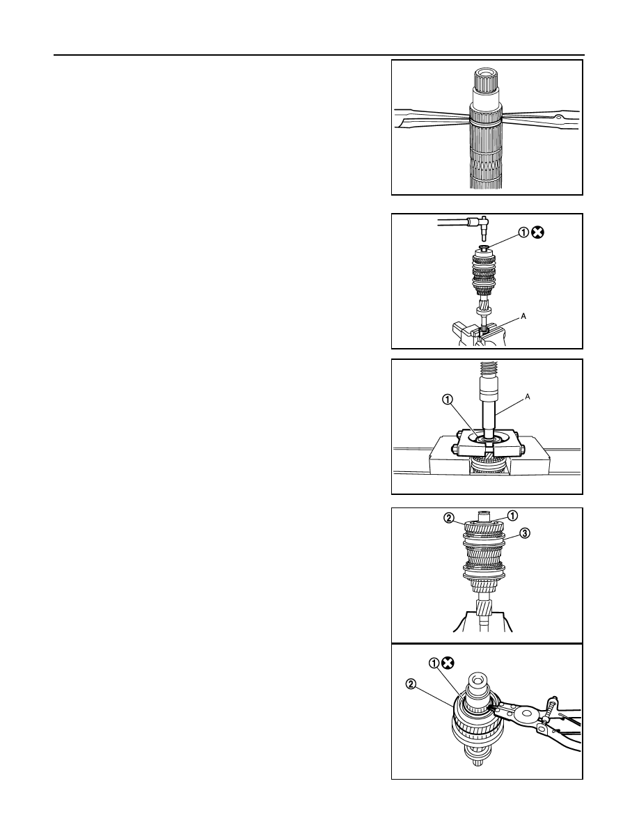
• For removal of snap ring, set snap ring pliers and flat pliers at
both sides of snap ring. While expanding snap ring with snap
ring pliers, move snap ring with flat pliers.
• Disassemble gear components putting direction marks on the
parts that do not affect any functions.
1. Remove input shaft rear bearing bolt (1), using Tool (A).
CAUTION:
Do not reuse rear bearing bolt.
2. Remove input shaft rear bearing (1) with the following proce-
dure.
a. Set a suitable tool to input shaft rear bearing.
b. Remove input shaft rear bearing using suitable tool (A).
3. Remove spacer (1), 6th input gear (2), needle bearing, 6th baulk
ring, and 5th-6th synchronizer hub assembly (3).
4. Remove insert keys and 5th-6th coupling sleeve from 5th-6th
synchronizer hub.
5. Remove snap ring (1).
CAUTION:
Do not reuse snap ring.
6. Remove spacer, 5th baulk ring, 5th input gear (2), and spacer.
SCIA1755J
Tool number (A)
: KV32300QAM (
—
)
JPDIC0449ZZ
JPDIC0111ZZ
PCIB1750E
PCIB1754E