Nissan Sentra. Manual - part 852


  Index      Nissan     Nissan Sentra (2014 year) - Service and Repair Manual


Search            


Content   ..  850  851  852  853   ..


Nissan Sentra. Manual - part 852


TM-44

< UNIT DISASSEMBLY AND ASSEMBLY >

[6MT: RS6F94R]

TRANSAXLE ASSEMBLY

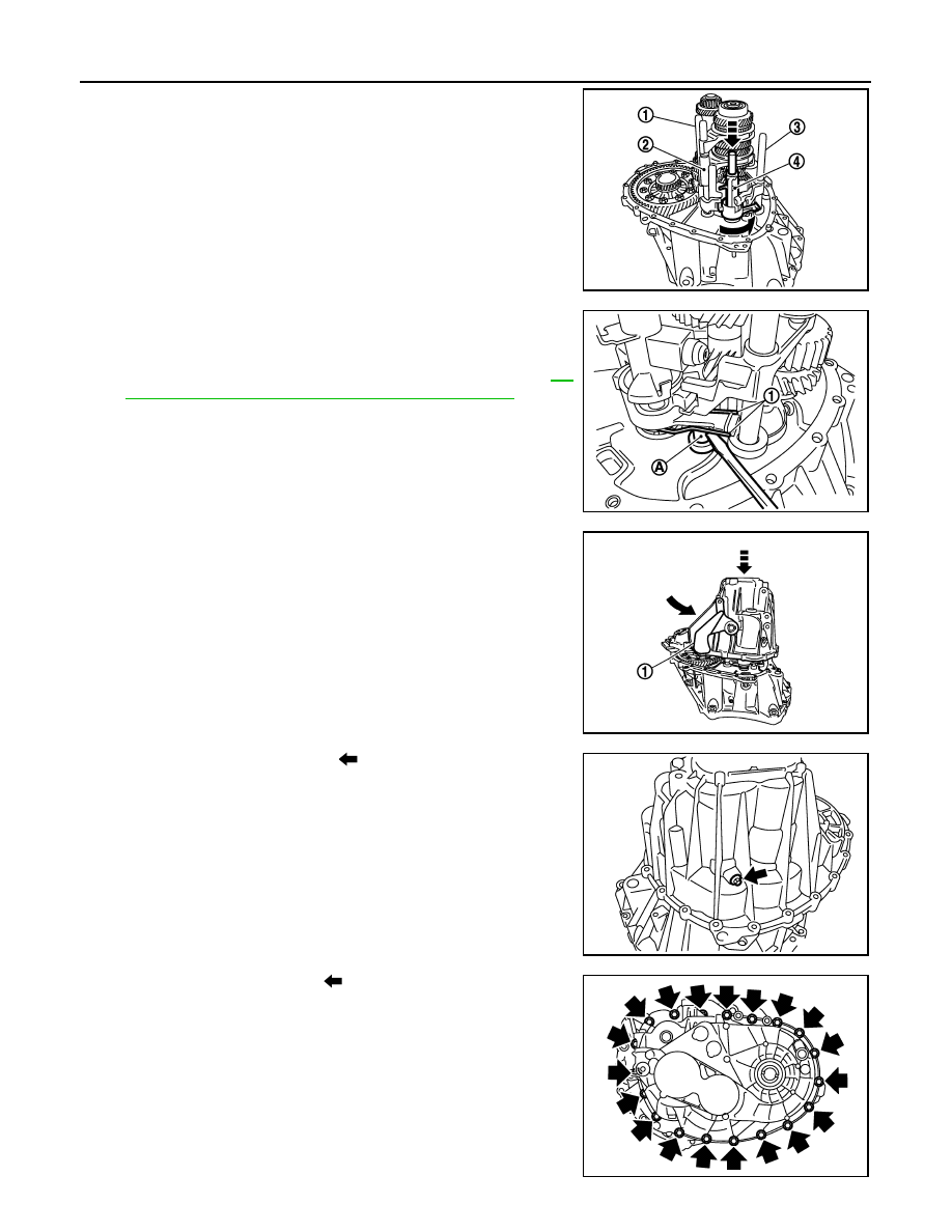
23. Move 1st-2nd fork rod (1), fork rod (2), and reverse fork rod (3)

to the neutral position.

24. Install selector (4) to clutch housing.

CAUTION:

Replace selector lever and selector as a set.

25. Install selector spring (1) to return bushing (A).
26. Apply recommended sealant to the gasket surface of transaxle

case.

• Use Genuine Silicone RTV or an equivalent. Refer to 

GI-

21, "Recommended Chemical Products and Sealants"

.

CAUTION:

• Do not allow old liquid gasket, moisture, oil, or foreign

matter to remain on gasket surface.

• Check that the gasket surface is not damaged.

• Apply sealant bead continuously.

27. Install transaxle case to clutch housing while rotating shifter

lever A (1) in the direction as shown.

28. Install reverse idler shaft bolt (

), as per the following proce-

dure.

a. Install sealing washer to reverse idler shaft bolt, and install

reverse idler shaft bolt to transaxle case.

CAUTION:

Do not reuse sealing washer.

b. Tighten reverse idler shaft bolt to the specified torque. 

29. Tighten transaxle case bolts (

) to the specified torque.

SCIA7782E

JPDIC0445ZZ

JPDIC0110ZZ

PCIB1695E

PCIB1694E

TRANSAXLE ASSEMBLY

TM-45

< UNIT DISASSEMBLY AND ASSEMBLY >

[6MT: RS6F94R]

C

E

F

G

H

I

J

K

L

M

A

B

TM

N

O

P

30. Install position switch (1), with the following procedure.
a. Apply recommended sealant to threads of position switch.

• Use Genuine Silicone RTV or an equivalent.Refer to 

GI-21,

"Recommended Chemical Products and Sealants"

.

CAUTION:

Do not allow old liquid gasket, moisture, oil, or foreign mat-

ter to remain on thread.

b. Install position switch to transaxle case and tighten it to the

specified torque.

31. Install bracket (2) to transaxle case and tighten bolt to the speci-

fied torque.

32. Install selector lever (3) with the following procedure.
a. Install selector lever to transaxle case.

CAUTION:

Replace selector lever and selector as a set.

b. Install retaining pin to selector lever using a suitable tool.

CAUTION:

Do not reuse retaining pin.

33. Install drain plug with the following procedure.
a. Install gasket to drain plug.

CAUTION:

Do not reuse gasket.

b. Install drain plug to clutch housing using a suitable tool.
c. Tighten drain plug to the specified torque.

CAUTION:

Do not overtighten drain plug as this could cause the transaxle case to crack.

34. Install filler plug with the following procedure.
a. Install gasket to filler plug and install it to the transaxle case.

CAUTION:

Do not reuse gasket.

b. Tighten filler plug to the specified torque.

CAUTION:

Fill with gear oil before tighten filler plug to the specified torque.

Do not overtighten the filler plug as this could cause the transaxle case to crack.

Inspection

INFOID:0000000009759290

INSPECTION AFTER DISASSEMBLY

SCIA7784E

TM-46

< UNIT DISASSEMBLY AND ASSEMBLY >

[6MT: RS6F94R]

TRANSAXLE ASSEMBLY

Check contact surface (

) and sliding surface (

) for excessive

wear, uneven wear, bend, and damage. Replace if necessary.

SCIA7785E

INPUT SHAFT AND GEAR

TM-47

< UNIT DISASSEMBLY AND ASSEMBLY >

[6MT: RS6F94R]

C

E

F

G

H

I

J

K

L

M

A

B

TM

N

O

P

INPUT SHAFT AND GEAR

Exploded View

INFOID:0000000009759291

Disassembly

INFOID:0000000009759292

CAUTION:

• Fix input shaft in a vise with back plate, and then remove gears and snap rings.

1.

Input shaft front bearing

2.

Input shaft

3.

3rd input gear

4.

Spacer

5.

Snap ring

6.

3rd baulk ring

7.

3rd-4th coupling sleeve

8.

3rd-4th synchronizer hub

9.

Insert key

10.

4th baulk ring

11.

4th input gear

12. 5th input gear

13.

5th baulk ring

14.

5th-6th coupling sleeve

15. 5th-6th synchronizer hub

16.

6th baulk ring

17.

Needle bearing 

18. 6th input gear

19.

Input shaft rear bearing

A.

First step

B.

Final step

JPDIC0407GB


Content   ..  850  851  852  853   ..