Nissan Sentra. Manual - part 851


  Index      Nissan     Nissan Sentra (2014 year) - Service and Repair Manual


Search            


Content   ..  849  850  851  852   ..


Nissan Sentra. Manual - part 851


TM-40

< UNIT DISASSEMBLY AND ASSEMBLY >

[6MT: RS6F94R]

TRANSAXLE ASSEMBLY

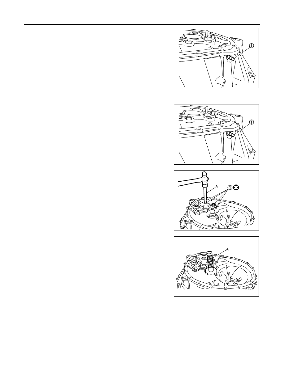
32. Remove 2 way connector (1) from clutch housing.

Assembly

INFOID:0000000009759289

1. Install 2 way connector (1) to clutch housing.

2. Install bushings (1) so that they becomes even with clutch hous-

ing surface, using suitable tool (A).

3. Install oil channel to clutch housing.

CAUTION:

Do not reuse oil channel.

4. Install mainshaft front bearing outer race to clutch housing using

Tool (A).

CAUTION:

Replace mainshaft front bearing outer race and mainshaft

front bearing inner race as a set.

Do not reuse mainshaft front bearing inner or outer race.

5. Install input shaft oil seal (1) to clutch housing using the Tool (A).

PCIB1720E

PCIB1720E

JPDIC0108ZZ

Tool number (A) : KV38100200 (

)

PCIB1724E

TRANSAXLE ASSEMBLY

TM-41

< UNIT DISASSEMBLY AND ASSEMBLY >

[6MT: RS6F94R]

C

E

F

G

H

I

J

K

L

M

A

B

TM

N

O

P

6. Install snap ring (1) and oil channel (2) to transaxle case.

CAUTION:

• Select and install snap ring that has the same thickness

as previous one.

• Replace transaxle assembly when replacing transaxle

case.

7. Install mainshaft rear bearing adjusting shim to transaxle case.

CAUTION:

Select mainshaft rear bearing adjusting shim, with the fol-

lowing procedure when replacing mainshaft adjusting

shim, 6th main gear, 5th main gear, or 4th main gear.

• Replace mainshaft adjusting shim.

- If new mainshaft adjusting shim is thinner than previous one, offset the thickness difference by

selecting thicker mainshaft rear bearing adjusting shim.

- If new mainshaft adjusting shim is thicker than previous one, offset the thickness difference by

selecting thinner mainshaft rear bearing adjusting shim.

• Replace 6th main gear, 5th main gear, or 4th main gear.

- Measure the thickness of the main gear used before and the new main gear

- Increase the thickness of the mainshaft rear bearing adjusting shim, if the difference is smaller

than 0.025 mm (0.0010 in).

- Decrease the thickness of the mainshaft rear bearing adjusting shim, if the difference is greater

than 0.025 mm (0.0010 in).

8. Install mainshaft rear bearing outer race to transaxle case using

suitable tool (A).

CAUTION:

Replace mainshaft rear bearing outer race and mainshaft

rear bearing inner race as a set.

9. Install bushings (1) to transaxle case, using suitable tool (A).

Tool number (A) : ST33220000 (

)

PCIB1721E

PCIB1729E

Tool number : KV38100200 (

)

PCIB1728E

JPDIC0109ZZ

TM-42

< UNIT DISASSEMBLY AND ASSEMBLY >

[6MT: RS6F94R]

TRANSAXLE ASSEMBLY

10. Install oil gutter (1) to transaxle case.

11. Install shifter lever B (1) to transaxle case.

CAUTION:

Replace shifter lever A and shifter lever B as a set.

12. Install shifter lever A to transaxle case.

CAUTION:

Replace shifter lever A and shifter lever B as a set.

13. Install retaining pin to shifter lever A (1) using a suitable tool.

CAUTION:

Do not reuse retaining pin.

14. Install shim to transaxle case.

15. Install differential side bearing outer race (transaxle case side)

to transaxle case, using Tool (A).

CAUTION:

Replace differential side bearing outer race (transaxle case

side) and differential side bearing inner race (transaxle case

side) as a set.

Do not reuse differential side bearing inner or outer race.

16. Install differential side bearing outer race (clutch housing side) to

clutch housing, using Tool (A).

CAUTION:

Replace differential side bearing outer race (clutch housing

side) and differential side bearing inner race (clutch hous-

ing side) as a set.

Do not reuse differential side bearing inner or outer race.

PCIB1730E

PCIB1712E

BCIA0047E

Tool number : ST33400001 (J-26082)

PCIB1726E

Tool number  : KV38100200 (

)

PCIB1722E

TRANSAXLE ASSEMBLY

TM-43

< UNIT DISASSEMBLY AND ASSEMBLY >

[6MT: RS6F94R]

C

E

F

G

H

I

J

K

L

M

A

B

TM

N

O

P

17. Install differential side oil seals (1) to clutch housing and tran-

saxle case, using Tools.

CAUTION:

• Do not incline differential side oil seal.

• Do not damage clutch housing and transaxle case.

18. Install magnet to clutch housing.
19. Install final drive assembly to clutch housing.
20. Set fork rod (1) to input shaft assembly (2), and then install them

to clutch housing.

21. Install mainshaft assembly (1), with the following procedure.
a. Pull up input shaft assembly (2) and fork rod (3).
b. Set 1st-2nd fork rod (4) to mainshaft assembly and install them

to clutch housing.

22. Install reverse idler shaft assembly (1) with the following proce-

dure.

a. Install spring washer to clutch housing.
b. Pull up input shaft assembly (2), mainshaft assembly (3), fork

rod (4), and 1st-2nd fork rod (5).

NOTE:

It is easier to pull up when shifting each fork rod to each shaft

side.

c. Set reverse fork rod (6) to reverse idler shaft assembly and

install them to clutch housing.

Tool number : KV32500QAA
Tool number : B.vi 1666-B

(A)

: Transaxle case side

(B)

: Clutch housing side

Dimension (L

1

)

: 1.2 – 1.8 mm (0.047 – 0.071 in) 

Dimension (L

2

)

: 2.7 – 3.3 mm (0.106 – 0.130 in)

JPDIC0454ZZ

JPDIC0608ZZ

JPDIC0609ZZ

JPDIC0606ZZ


Content   ..  849  850  851  852   ..