Nissan Leaf. Manual - part 748
HA-114
< REMOVAL AND INSTALLATION >
[WITHOUT HEAT PUMP SYSTEM]
HEATING AND COOLING UNIT ASSEMBLY
HEATING AND COOLING UNIT ASSEMBLY
HEATING AND COOLING UNIT ASSEMBLY : Removal and Installation
INFOID:0000000010122182
DANGER:
Since hybrid vehicles and electric vehicles contain a high voltage battery, there is the risk of
electric shock, electric leakage, or similar accidents if the high voltage component and vehicle are
handled incorrectly. Be sure to follow the correct work procedures when performing inspection and
maintenance.
WARNING:
• Be sure to remove the service plug in order to disconnect the high voltage circuits before perform-
ing inspection or maintenance of high voltage system harnesses and parts.
• The removed service plug must always be carried in a pocket of the responsible worker or placed in
the tool box during the procedure to prevent the plug from being connected by mistake.
• Be sure to wear insulating protective equipment consisting of glove, shoes, face shield and glasses
before beginning work on the high voltage system.
• Never allow workers other than the responsible person to touch the vehicle containing high voltage
parts. To keep others from touching the high voltage parts, these parts must be covered with an insu-
lating sheet except when using them. Refer to
GI-34, "High Voltage Precautions"
CAUTION:
Never bring the vehicle into the READY status with the service plug removed unless otherwise
instructed in the Service Manual. A malfunction may occur if this is not observed.
REMOVAL
WARNING:
Disconnect high voltage circuit. Refer to
GI-33, "How to Disconnect High Voltage"
.
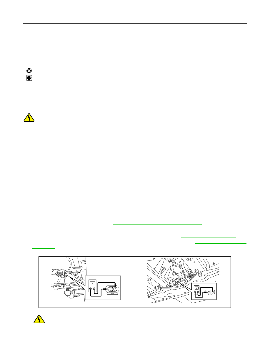
1. Check voltage in high voltage circuit. (Check that condenser are discharged.)
a. Lift up the vehicle, and then remove Li-ion battery under covers. Refer to
b. Disconnect high voltage connector from front side of Li-ion battery. Refer to
.
c.
Measure voltage between high voltage harness terminals.
DANGER:
Touching high voltage components without using the appropriate protective equipment will
cause electrocution.
28. Lower air mix door
29. Upper air mix door
30. Air mix door guide
31. Foot door rod
32. Side ventilator door
33. Foot door
34. Side ventilator door seal LH
35. Lower attachment case
36. Side ventilator seal RH
37. Center ventilator and defroster door
38. Sub defroster door
39. Upper attachment case
40. Defroster seal
41. Ventilator seal
42. Intake seal
43. Lower intake case
44. Intake door
45. Upper intake case
46. Power transistor
47. Sub harness
: Always replace after every disassembly.
: N·m (kg-m, in-lb)
JPCIA0296ZZ