Nissan Leaf. Manual - part 747


  Index      Nissan     Nissan Leaf (2011-2014 year) - Service and Repair Manual


Search            


Content   ..  745  746  747  748   ..


Nissan Leaf. Manual - part 747


HA-110

< REMOVAL AND INSTALLATION >

[WITHOUT HEAT PUMP SYSTEM]

CONDENSER

LIQUID TANK : Removal and Installation

INFOID:0000000010122179

DANGER:

Since hybrid vehicles and electric vehicles contain a high voltage battery, there is the risk of

electric shock, electric leakage, or similar accidents if the high voltage component and vehicle are

handled incorrectly. Be sure to follow the correct work procedures when performing inspection and

maintenance.

WARNING:

• Be sure to remove the service plug in order to disconnect the high voltage circuits before perform-

ing inspection or maintenance of high voltage system harnesses and parts.

• The removed service plug must always be carried in a pocket of the responsible worker or placed in

the tool box during the procedure to prevent the plug from being connected by mistake.

• Be sure to wear insulating protective equipment consisting of glove, shoes, face shield and glasses

before beginning work on the high voltage system.

• Never allow workers other than the responsible person to touch the vehicle containing high voltage

parts. To keep others from touching the high voltage parts, these parts must be covered with an insu-

lating sheet except when using them. Refer to 

GI-34, "High Voltage Precautions"

.

CAUTION:

Never bring the vehicle into the READY status with the service plug removed unless otherwise

instructed in the Service Manual. A malfunction may occur if this is not observed.

REMOVAL

1. Use the refrigerant recovery equipment (for HFC134a) and recover the refrigerant. Refer to 

HA-85, "Recy-

cle Refrigerant"

.

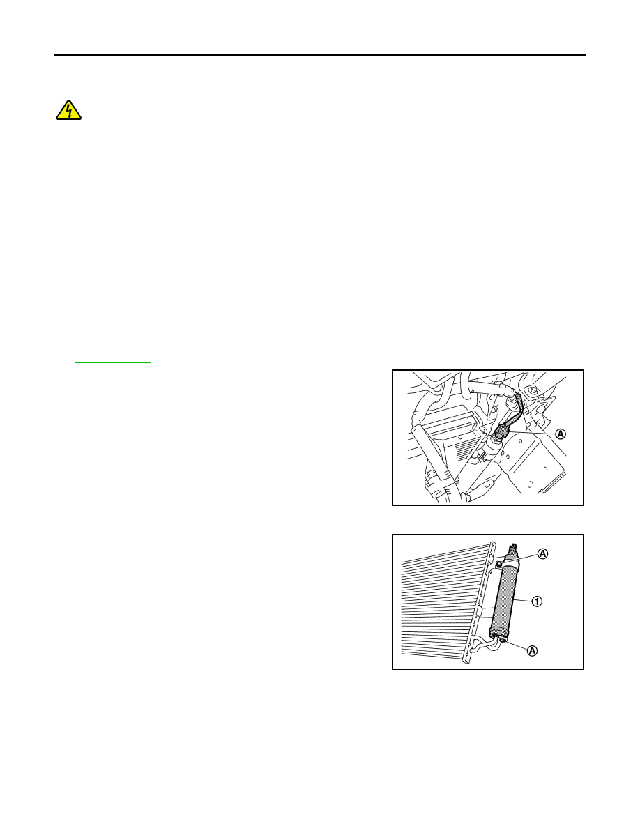
2. Disconnect refrigerant pressure sensor connector (A).

3. Clean around the liquid tank to remove any dirt or corrosion.
4. Remove bolts (A), and then remove liquid tank (1) from con-

denser.

CAUTION:

To prevent the inclusion of foreign matter, use a cap or vinyl

tape to seal off the connection ports of the liquid tank and

condenser from the atmosphere.

INSTALLATION

Note the following items, and then install in the reverse order of removal.

CAUTION:

• To prevent degradation in insulation performance, use special electric compressor oil as the com-

pressor oil.

• In order to prevent conventional PAG oil from becoming mixed in, never reuse recovered compres-

sor oil and instead always use new oil. The use of oil including the conventional PAG oil may

degrade the performance of insulation.

JPIIA1775ZZ

JPIIA1777ZZ

CONDENSER

HA-111

< REMOVAL AND INSTALLATION >

[WITHOUT HEAT PUMP SYSTEM]

C

D

E

F

G

H

J

K

L

M

A

B

HA

N

O

P

• To prevent performance degradation, never use a fluorescent agent in order to detect refrigerant

leakage. Also be careful that a fluorescent agent never enter the oil.

• After installing a new liquid tank, adjust the compressor oil level. Refer to 

HA-87, "Lubricant Adjust-

ing Procedure for Components Replacement Except Compressor"

.

• To prevent leakage of refrigerant, replace the O-ring with a new one. Apply a coat of compressor oil

to the O-ring prior to installation.

• Perform a check for refrigerant leakage when charging with refrigerant. Refer to 

HA-84, "Check

Refrigerant Leakage"

.

REFRIGERANT PRESSURE SENSOR
REFRIGERANT PRESSURE SENSOR : Removal and Installation

INFOID:0000000010122180

DANGER:

Since hybrid vehicles and electric vehicles contain a high voltage battery, there is the risk of

electric shock, electric leakage, or similar accidents if the high voltage component and vehicle are

handled incorrectly. Be sure to follow the correct work procedures when performing inspection and

maintenance.

WARNING:

• Be sure to remove the service plug in order to disconnect the high voltage circuits before perform-

ing inspection or maintenance of high voltage system harnesses and parts.

• The removed service plug must always be carried in a pocket of the responsible worker or placed in

the tool box during the procedure to prevent the plug from being connected by mistake.

• Be sure to wear insulating protective equipment consisting of glove, shoes, face shield and glasses

before beginning work on the high voltage system.

• Never allow workers other than the responsible person to touch the vehicle containing high voltage

parts. To keep others from touching the high voltage parts, these parts must be covered with an insu-

lating sheet except when using them. Refer to 

GI-34, "High Voltage Precautions"

.

CAUTION:

Never bring the vehicle into the READY status with the service plug removed unless otherwise

instructed in the Service Manual. A malfunction may occur if this is not observed.

REMOVAL

1. Remove liquid tank. Refer to 

HA-110, "LIQUID TANK : Removal and Installation"

.

2. Use a vise (A) to fasten the liquid tank (1) in place, then use a

spanner wrench (B) and remove refrigerant pressure sensor (2).

CAUTION:

• Wrap the liquid tank with shop cloth to prevent scratches.

• To prevent the inclusion of foreign matter, use a cap or

vinyl tape to seal off the refrigerant pressure sensor

mounting point on the liquid tank from the atmosphere.

INSTALLATION

Note the following items, and then install in the reverse order of removal.

CAUTION:

• To prevent leakage of refrigerant, replace the O-ring with a new one. Apply a coat of compressor oil

to the O-ring prior to installation.

• Perform a check for refrigerant leakage when charging with refrigerant. Refer to 

HA-84, "Check

Refrigerant Leakage"

.

JSIIA0075ZZ

HA-112

< REMOVAL AND INSTALLATION >

[WITHOUT HEAT PUMP SYSTEM]

HEATING AND COOLING UNIT ASSEMBLY

HEATING AND COOLING UNIT ASSEMBLY

Exploded View

INFOID:0000000010122181

REMOVAL

DISASSEMBLY

1.

Heating and cooling unit assembly

2.

Drain hose

3.

Instrument stay

4.

Steering member

 : Clip

 : N·m (kg-m, in-lb)

 : N·m (kg-m, ft-lb)

AWIIA1657ZZ

HEATING AND COOLING UNIT ASSEMBLY

HA-113

< REMOVAL AND INSTALLATION >

[WITHOUT HEAT PUMP SYSTEM]

C

D

E

F

G

H

J

K

L

M

A

B

HA

N

O

P

1.

Blower motor

2.

Blower case RH

3.

Blower case LH

4.

High voltage warning label

5.

PTC heater shield RH 

6.

PTC heater

7.

Heating and cooling unit assembly 
case RH

8.

Case packing

9.

Evaporator

10. Plate

11. O-rings

12. Grommet

13. Expansion valve

14. Intake sensor

15. PTC heater shield lower

16. Evaporator cover

17. Gasket

18. Seal

19. PTC elements heater shield LH

20. PTC heater outlet and A/C unit case 

air temperature sensor assembly

21. Heating and cooling unit assembly 

case LH

22. Filter cover

23. Filter

24. Aspirator

25. Aspirator tube

26. Harness

27. PTC heater shield

JMIIA2631GB


Content   ..  745  746  747  748   ..