Nissan Leaf. Manual - part 396


  Index      Nissan     Nissan Leaf (2011-2014 year) - Service and Repair Manual


Search            


Content   ..  394  395  396  397   ..


Nissan Leaf. Manual - part 396


B2628 OUTSIDE ANTENNA

DLK-79

< DTC/CIRCUIT DIAGNOSIS >

C

D

E

F

G

H

I

J

L

M

A

B

DLK

N

O

P

1. Disconnect BCM connector and outside key antenna (rear bumper) connector.

2. Check continuity between BCM harness connector and outside key antenna (rear bumper) harness con-

nector.

3. Check continuity between BCM harness connector and ground.

Is the inspection result normal?

YES

>> GO TO 3.

NO

>> Repair or replace harness.

3.

CHECK OUTSIDE KEY ANTENNA INPUT SIGNAL 2

1. Replace outside key antenna (rear bumper). (New antenna or other antenna)

2. Connect BCM and outside key antenna (rear bumper) connector.

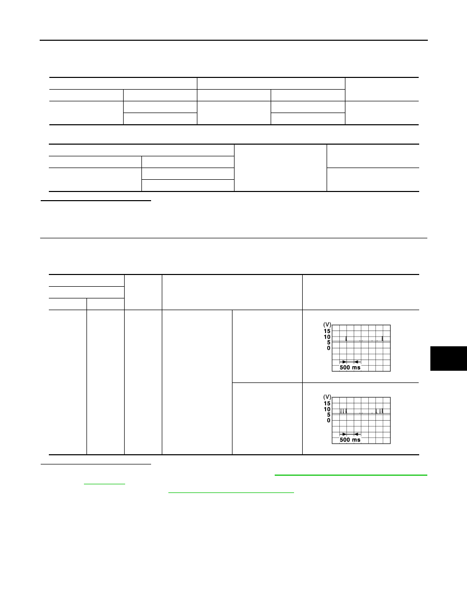
3. Check signal between BCM harness connector and ground using oscilloscope.

Is the inspection result normal?

YES

>> Replace outside key antenna (rear bumper). Refer to 

DLK-207, "REAR BUMPER : Removal and

Installation"

.

NO

>> Replace BCM. Refer to 

BCS-72, "Removal and Installation"

.

BCM

Outside key antenna (rear bumper)

Continuity 

Connector

Terminal

Connector

Terminal

M23

82

B83

1

Yes

83

2

BCM

Ground

Continuity 

Connector

Terminal

M23

82

No

83

(+)

(–)

Condition

Signal

(Reference value)

BCM

Connector

Terminal

M23

82
83

Ground

When the back door 
request switch is oper-
ated with power 
switch OFF

When Intelligent Key 
is in the antenna de-
tection area (The dis-
tance between 
Intelligent Key and an-
tenna: 80 cm or less)

When Intelligent Key 
is not in the antenna 
detection area (The 
distance between In-
telligent Key and an-
tenna: Approx. 2 m)

JMKIA5955GB

JMKIA5954GB

DLK-80

< DTC/CIRCUIT DIAGNOSIS >

BACK DOOR OPENER ACTUATOR

BACK DOOR OPENER ACTUATOR

Component Function Check

INFOID:0000000010119753

1.

CHECK FUNCTION

1. Select “INTELLIGENT KEY” of “BCM” using CONSULT.

2. Select “TRUNK/BACK DOOR” in “Active Test”.

3. Touch “OPEN” to check that it works normally.
Is the inspection result normal?

YES

>> Back door opener actuator is OK.

NO

>> Refer to 

DLK-80, "Diagnosis Procedure"

.

Diagnosis Procedure

INFOID:0000000010119754

Regarding Wiring Diagram information, refer to 

DLK-44, "Wiring Diagram"

.

1.

CHECK BACK DOOR OPENER ACTUATOR INPUT SIGNAL

1. Turn power switch OFF.

2. Disconnect back door lock assembly connector.

3. Check voltage between back door lock assembly harness connector and ground.

Is the inspection result normal?

YES

>> GO TO 3.

NO

>> GO TO 2.

2.

CHECK BACK DOOR OPENER ACTUATOR CIRCUIT

1. Disconnect BCM connector.

2. Check continuity between BCM harness connector and back door lock assembly harness connector. 

3. Check continuity between BCM harness connector and ground.

Is the inspection result normal?

YES

>> Replace BCM. Refer to 

BCS-72, "Removal and Installation"

.

NO

>> Repair or replace harness.

3.

CHECK BACK DOOR OPENER ACTUATOR GROUND CIRCUIT

Check continuity between back door lock assembly harness connector and ground.

(+)

(–)

Condition

Voltage

(Approx.)

Back door lock assembly

Connector

Terminal

D562

1

Ground

Back door 
opener switch

ON

Battery voltage

BCM

Back door lock assembly

Continuity 

Connector

Terminal

Connector

Terminal

M29

53

D562

1

Yes

BCM

Ground

Continuity 

Connector

Terminal

M29

53

No

BACK DOOR OPENER ACTUATOR

DLK-81

< DTC/CIRCUIT DIAGNOSIS >

C

D

E

F

G

H

I

J

L

M

A

B

DLK

N

O

P

Is the inspection normal?

YES

>> Replace back door lock assembly. Refer to 

DLK-200, "DOOR LOCK : Removal and Installation"

.

NO

>> Repair or replace harness.

Back door lock assembly

Ground

Continuity

Connector

Terminal

D562

2

Yes

DLK-82

< DTC/CIRCUIT DIAGNOSIS >

BACK DOOR OPENER SWITCH

BACK DOOR OPENER SWITCH

Component Function Check

INFOID:0000000010119755

1.

CHECK FUNCTION

1. Select “TRUNK” of “BCM” using CONSULT.

2. Select “TR/BD OPEN SW” in “Data Monitor”.

3. Check that the function operates normally according to the following conditions:

Is the inspection result normal?

YES

>> Back door opener switch is OK.

NO

>> Refer to 

DLK-82, "Diagnosis Procedure"

.

Diagnosis Procedure

INFOID:0000000010119756

Regarding Wiring Diagram information, refer to 

DLK-44, "Wiring Diagram"

.

1.

CHECK BACK DOOR OPENER SWITCH INPUT SIGNAL

1. Turn power switch OFF.

2. Disconnect back door opener switch assembly connector.

3. Check signal between back door opener switch assembly harness connector and ground using oscillo-

scope.

Is the inspection result normal?

YES

>> GO TO 3.

NO

>> GO TO 2.

2.

CHECK BACK DOOR OPENER SWITCH CIRCUIT

1. Disconnect BCM connector.

2. Check continuity between BCM harness connector and back door opener switch assembly harness con-

nector.

3. Check continuity between BCM harness connector and ground.

Monitor item

Condition

Status

TR/BD OPEN SW

Back door opener switch

Pressed

ON

Released

OFF

(+)

(–)

Signal

(Reference value)

Back door opener switch assembly 

Connector

Terminal 

D563

1

Ground

JPMIA0012GB

BCM

Back door opener switch assembly

Continuity 

Connector

Terminal

Connector

Terminal

M24

30

D563

1

Yes


Content   ..  394  395  396  397   ..