Nissan Primera P11. Manual - part 545


  Index      Nissan     Nissan Primera P11 (2001 year) - Service and Repair Manual


Search            


Content   ..  543  544  545  546   ..


Nissan Primera P11. Manual - part 545


7. Malfunctioning part is indicated by the number of flashes

(part

p

d

or

p

f

). Compare the number of flashes to “Air Bag

Warning Lamp Flash Code Chart”, page RS-50, and locate
malfunctioning part.

8. Turn ignition switch “OFF”, and disconnect both battery

cables.

9. Repair the system as outlined by the “Repair order” in “Warn-

ing Lamp Flash Code Chart” that corresponds to the flash
code. For replacement procedure of component parts, refer
to RS-13.

10. After repairing the system, go to DIAGNOSTIC PROCE-

DURE 7, page RS-53.

No.

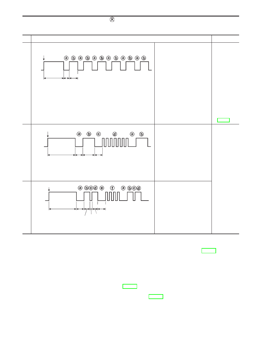
“AIR BAG” warning lamp flash pattern — Diagnosis mode —

SRS condition

1

SRS333

p

a

through

p

b

are repeated.

Diagnosis
results (pre-
viously
stored in the
memory)
might not be
erased after
repair.

Intermittent
malfunction
has been
detected in
the past.

Go to DIAG-
NOSTIC
PROCEDURE
(RS-55).

2

SRS341

p

a

through

p

d

are repeated.

p

b

— Driver and passenger’s

air bag marker (For identifying
driver’s passenger’s air bag
and/or front seat belt pre-ten-
sioner malfunctioning)

p

d

— Indicates malfunctioning

part. The number of flash var-
ies with malfunctioning part
(0.5 sec. ON and 0.5 sec. OFF
is counted as one flash.)

The system is
malfunctioning
and needs to
be repaired.

3

SRS342-A

p

a

through

p

f

are repeated.

p

b

,

p

c

,

p

d

— Side air bag

marker (For identifying side air
bag malfunctioning)

p

f

— Indicates malfunctioning

part. The number of flash var-
ies with malfunctioning part
(0.5 sec. ON and 0.5 sec. OFF
is counted as one flash.)

IGN ON

ON

OFF

7 sec.

3 sec.

2 sec.

IGN ON

ON

OFF

7 sec.

3 sec.

2 sec.

2 sec.

0.5 sec.

1.5 sec.

IGN ON

ON

OFF

7 sec.

2sec.

1.5 sec.

2 sec.

TROUBLE DIAGNOSES — Supplemental Restraint System (SRS)

Trouble Diagnoses without CONSULT-II

(Cont’d)

RS-49

Air Bag Warning Lamp Flash Code Chart (Diagnosis
mode)

Diagnosis results (previ-
ously stored in the
memory) might not be
erased after repair.

Intermittent malfunction
has been detected in the
past.

Flash pattern

SRS333

p

a

through

p

b

are repeated.

Repair order

Go to DIAGNOSTIC PROCEDURE 8 (RS-55).

The driver’s air bag module
circuit is malfunctioning.
(

p

d

: 2 flashes)

Flash pattern

SRS334

p

a

through

p

d

are repeated.

p

d

— Two flashes

indicated malfunc-
tioning driver’s air
bag module circuit.

Repair order (“Recheck SRS at each replacement.”)

1. Visually check the wiring harness connection.
2. Replace the harness if it has visible damage.
3. Replace the spiral cable.
4. Replace driver’s air bag module.

(Before disposal, it must be deployed.)

5. Replace the diagnosis sensor unit.
6. Replace the related harness.

The diagnosis sensor unit is
malfunctioning.
(

p

d

: 7 flashes)

Flash pattern

SRS335

p

a

through

p

d

are repeated.

p

d

— Seven

flashes indicate
malfunctioning diag-
nosis sensor unit.

Repair order (“Recheck SRS at each replacement.”)

1. Visually check the wiring harness connection.
2. Replace the harness if it has visible damage.
3. Replace the diagnosis sensor unit.
4. Replace the related harness.

IGN ON

ON

OFF

7 sec.

3 sec.

2 sec.

IGN ON

ON

OFF

7 sec.

3 sec.

2 sec.

2 sec.

IGN ON

ON

OFF

7 sec.

2 sec.

1.5 sec.

2 sec.

TROUBLE DIAGNOSES — Supplemental Restraint System (SRS)

Trouble Diagnoses without CONSULT-II

(Cont’d)

RS-50

The passenger’s air bag
module circuit is malfunc-
tioning.
(

p

d

: 8 flashes)

Flash pattern

SRS336

p

a

through

p

d

are repeated.

p

d

— Eight

flashes indicated
malfunctioning pas-
senger’s air bag
module circuit.

Repair order (“Recheck SRS at each replacement.”)

1. Visually check the wiring harness connection.
2. Replace the harness if it has visible damage.
3. Replace passenger’s air bag module.

(Before disposal, it must be deployed.)

4. Replace the diagnosis sensor unit.
5. Replace the related harness.

The RH seat belt pre-ten-
sioner circuit is malfunction-
ing. (

p

d

1 flash)

Flash pattern

SRS801

p

a

through

p

d

are repeated.

p

d

— One flash

indicates malfunc-
tioning RH seat belt
pre-tensioner cir-
cuit.

Repair order (“Recheck SRS at each replacement.”)

1. Visually check the wiring harness connection.
2. Replace the harness if it has visible damage.
3. Replace RH seat belt pre-tensioner.

(Before disposing, it must be deactivated.)

4. Replace the diagnosis sensor unit.
5. Replace the related harness.

The LH seat belt pre-ten-
sioner circuit is malfunction-
ing. (

p

d

3 flash)

Flash pattern

SRS802

p

a

through

p

d

are repeated.

p

d

— Three flash

indicates malfunc-
tioning LH seat belt
pre-tensioner cir-
cuit.

Repair order (“Recheck SRS at each replacement.”)

1. Visually check the wiring harness connection.
2. Replace the harness if it has visible damage.
3. Replace LH seat belt pre-tensioner.

(Before disposing, it must be deactivated.)

4. Replace the diagnosis sensor unit.
5. Replace the related harness.

3 sec.

IGN ON

ON

OFF

7 sec.

2 sec.

3 sec.

IGN ON

ON

OFF

7 sec.

2 sec.

2 sec.

2 sec.

IGN ON

ON

OFF

7 sec.

2 sec.

2 sec.

3 sec.

TROUBLE DIAGNOSES — Supplemental Restraint System (SRS)

Trouble Diagnoses without CONSULT-II

(Cont’d)

RS-51

The side air bag module
(RH) circuit is malfunction-
ing.
(

p

f

: 1 flash)

Flash pattern

SRS338

p

a

through

p

f

are repeated.

p

f

— One flash

indicates malfunc-
tioning side air bag
module (RH) circuit.

Repair order (“Recheck SRS at each replacement.”)

1. Visually check the wiring harness connection.
2. Replace the harness if it has visible damage.
3. Replace side air bag module (RH).

(Before disposal, it must be deployed.)

4. Replace the diagnosis sensor unit.
5. Replace the related harness.

The side air bag module
(LH) circuit is malfunction-
ing.
(

p

f

: 2 flashes)

Flash pattern

SRS337

p

a

through

p

f

are repeated.

p

f

— Two flashes

indicate malfunc-
tioning side air bag
module (LH) circuit.

Repair order (“Recheck SRS at each replacement.”)

1. Visually check the wiring harness connection.
2. Replace the harness if it has visible damage.
3. Replace side air bag module (LH).

(Before disposal, it must be deployed.)

4. Replace the diagnosis sensor unit.
5. Replace the related harness.

The satellite sensor (RH) is
malfunctioning.
(

p

f

: 3 flashes)

Flash pattern

SRS340

p

a

through

p

f

are repeated.

p

f

— Three

flashes indicated
malfunctioning sat-
ellite sensor (RH)
circuit.

Repair order (“Recheck SRS at each replacement.”)

1. Visually check the wiring harness connection.
2. Replace the harness if it has visible damage.
3. Replace the satellite sensor (RH).
4. Replace the diagnosis sensor unit.
5. Replace the related harness.

IGN ON

ON

OFF

7 sec.

2 sec.

2 sec.

1.5 sec.

0.5 sec.

1.5 sec.

IGN ON

ON

OFF

7 sec.

2 sec.

1.5 sec.

0.5 sec.

1.5 sec.

2 sec.

IGN ON

ON

OFF

7 sec.

2 sec.

1.5 sec.

0.5 sec.

1.5 sec.

2 sec.

TROUBLE DIAGNOSES — Supplemental Restraint System (SRS)

Trouble Diagnoses without CONSULT-II

(Cont’d)

RS-52


Content   ..  543  544  545  546   ..