Nissan Primera P11. Manual - part 446
p
1
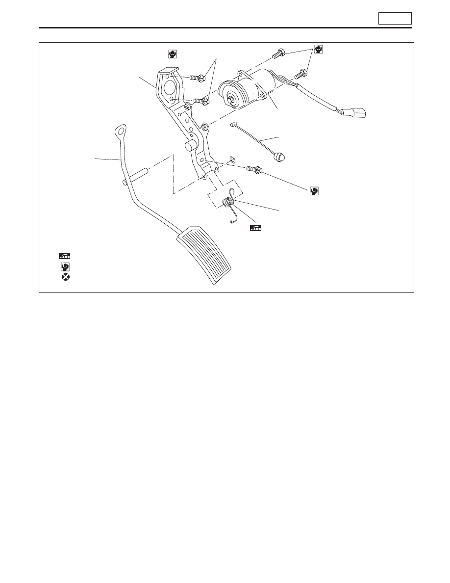
Pedal bracket
p
2
Accelerator position sensor
p
3
Accelerator cable
p
4
Return spring
p
5
Accelerator pedal
●
If MIL illuminates after engine has started, refer to “ON
BOARD DIAGNOSTIC SYSTEM DESCRIPTION” in EC
section for instructions.
NFE043
p
1
p
5
6 - 7 (0.61 - 0.71, 53.1 - 62.0)
p
4
p
3
p
2
2.9 - 3.9 (0.30 - 0.40, 25.7 - 34.5)
SEC. 180
: Apply grease
: N·m (kg-m, in-lb)
: Do not re-use
2.9 - 3.9 (0.3 - 0.4, 25.7 - 34.5)
ACCELERATOR CONTROL SYSTEM
CD20T
FE-5