Nissan Primera P11. Manual - part 443
INSPECTION
Shock absorber assembly
●
Check for smooth operation through a full stroke, both com-
pression and extension.
●
Check for oil leakage occurring on welded or gland packing
portions.
●
Check piston rod for cracks, deformation or other damage.
Replace if necessary.
Mounting insulator and rubber parts
●
Check cemented rubber-to-metal portion for separation or
cracks.
●
Check rubber parts for deterioration. Replace if necessary.
Coil spring
●
Check for cracks, deformation or other damage. Replace if
necessary.
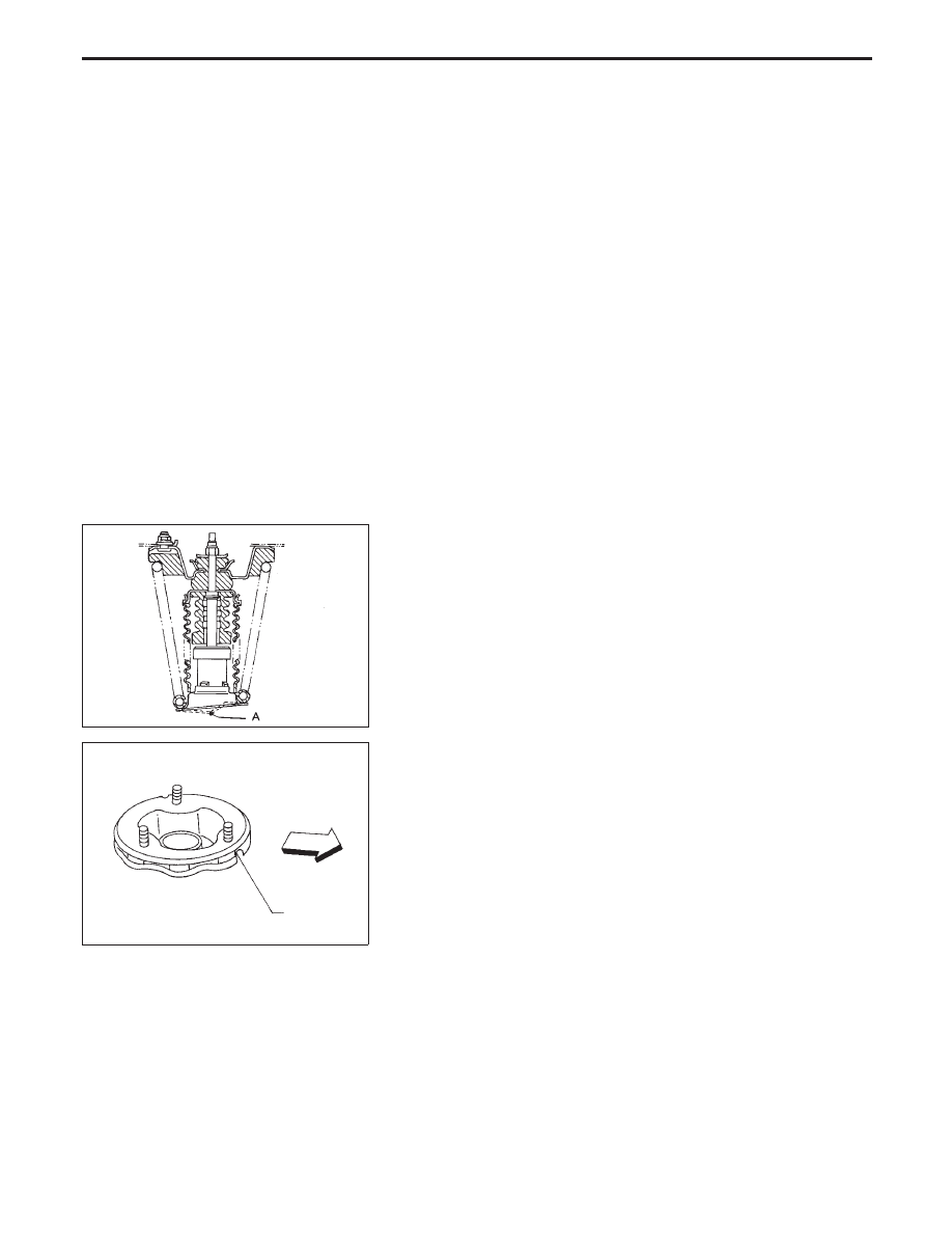
ASSEMBLY
●
When shock absorber is installed, it must be positioned so
that arrow point A faces rearward on LH side, and forward on
RH side.
●
Install upper spring seat with its cutout facing the inside of the
vehicle.
Third Link and Upper Link
REMOVAL
CAUTION:
Kingpin bearing usually does not require maintenance. If
any of the following symptoms are noted, replace kingpin
bearing assembly.
●
Growling noise is emitted from kingpin bearing during
operation.
●
Kingpin bearing drags or turns roughly when steering
knuckle is turned by hand.
SFA920A
SFA921A
Inside
Cutout
FRONT SUSPENSION
Coil Spring and Shock Absorber (Cont’d)
FA-29