Nissan Primera P11. Manual - part 414


  Index      Nissan     Nissan Primera P11 (2001 year) - Service and Repair Manual


Search            


Content   ..  412  413  414  415   ..


Nissan Primera P11. Manual - part 414


b.

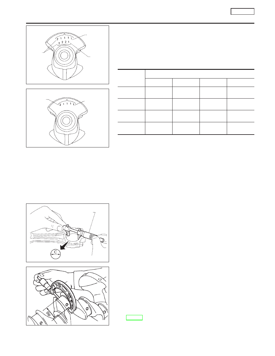
Grade number of each crankshaft main journal is punched on
the respective crankshaft. These numbers are punched in
either Arabic or Roman numerals.

c.

Select main bearing with suitable thickness according to the
following table.

How to select main bearings
(Identification mark and color)

Crankshaft
main journal
grade number

Cylinder block main journal grade number

0

1

2

3

0

0

(A, Black)

1

(B, Red)

2

(C, Green)

3

(D, Yellow)

1

1

(B, Red)

2

(C, Green)

3

(D, Yellow)

4

(E, Blue)

2

2

(C, Green)

3

(D, Yellow)

4

(E, Blue)

5

(F, Pink)

3

3

(D, Yellow)

4

(E, Blue)

5

(F, Pink)

6

(G, White)

For example:

Main journal grade number: 1
Crankshaft journal grade number: 2
Main bearing grade number = 1 + 2

= 3 (D, Yellow)

Connecting rod bearing (Big end)

1.

Install connecting rod bearing to connecting rod and cap.

2.

Install connecting rod cap to connecting rod.

Tighten bolts to the specified torque.
3.

Measure inner diameter “C” of each bearing.

4.

Measure outer diameter “Dp” of each crankshaft pin journal.

5.

Calculate connecting rod bearing clearance.
Connecting rod bearing clearance = C − Dp

Standard:

0.020 - 0.045 mm (0.0008 - 0.0018 in)

Limit:

0.065 mm (0.0026 in)

6.

If it exceeds the limit, replace bearing.

7.

If clearance cannot be adjusted within the standard of any
bearing, grind crankshaft journal and use undersized bearing.
Refer to step 7 of “BEARING CLEARANCE − Main bearing”
(EM-114).

SEM013D

Type I

Main journal grade number

No. 5

No. 4

No. 1

Crankshaft
front view

SEM203D

Type II

Main journal grade number

No. 1

No. 5 journal

Crankshaft
front view

AEM027

Inside micrometer

AEM028

CYLINDER BLOCK

SR20DE

Inspection (Cont’d)

EM-115

8.

If crankshaft is replaced with a new one, select connecting rod
bearing according to the following table.

Connecting rod bearing grade number:
These numbers are punched in either Arabic or Roman numerals.

Crank pin grade number

Connecting rod bearing grade

number

0

0

1

1

2

2

Identification color:

Grade 0; Black or Yellow
Grade 1; Brown or Red
Grade 2; Green or Blue

Method B (Using plastigage)

CAUTION:

I

Do not turn crankshaft or connecting rod while plastigage
is being inserted.

I

When bearing clearance exceeds the specified limit,
ensure that the proper bearing has been installed. If incor-
rect bearing clearance exists, use a thicker or undersized
main bearing to ensure specified clearance.

CONNECTING ROD BUSHING CLEARANCE (Small end)

1.

Measure inner diameter “C” of bushing.
Refer to SDS EM-193 - “CONNECTING ROD”.

2.

Measure outer diameter “Dp” of piston pin.

3.

Calculate connecting rod bushing clearance.
Connecting rod bushing clearance = C − Dp

Standard:

0.005 - 0.017 mm (0.0002 - 0.0007 in)

Limit:

0.023 mm (0.0009 in)

If it exceeds the limit, replace connecting rod assembly or
connecting rod bushing and/or piston set with pin.

SEM013D

Type I

Main journal grade number

No. 5

No. 4

No. 1

Crankshaft
front view

SEM204D

Type II

No. 1

No. 2

No. 3

No. 4 cylinder

Grade 0
Grade 1

Grade 2

Pin journal
grade number

Crankshaft
rear view

EM142

AEM029

AEM030

Micrometer

CYLINDER BLOCK

SR20DE

Inspection (Cont’d)

EM-116

REPLACEMENT OF CONNECTING ROD BUSHING
(Small end)

1.

Drive in small end bushing until it is flush with end surface of
rod.

Be sure to align the oil holes.
2.

After driving in small end bushing, ream the bushing. This is
to ensure the clearance between connecting rod bushing and
piston pin is the specified value.

Clearance between connecting rod bushing and pis-
ton pin:

0.005 - 0.017 mm (0.0002 - 0.0007 in)

REPLACEMENT OF PILOT BUSHING (M/T) OR PILOT
CONVERTER (CVT)

1.

Remove pilot bushing or pilot converter using Tool or suitable
tool.

2.

Install pilot bushing or pilot converter as shown.

FLYWHEEL/DRIVE PLATE RUNOUT

Runout (Total indicator reading):

Flywheel (M/T model)

Less than 0.15 mm (0.0059 in)

Drive plate (CVT model)

Less than 0.20 mm (0.0079 in)

CAUTION:

Do not allow any magnetic materials to contact the ring gear
teeth.

Assembly

PISTON

1.

Install new snap ring on one side of piston pin hole.

SEM062A

Align.

SEM916AB

SEM163B

M/T

Crankshaft side

CVT

.

SEM901E

SEM166B

CYLINDER BLOCK

SR20DE

Inspection (Cont’d)

EM-117

2.

Heat piston to 60 to 70°C (140 to 158°F) and assemble piston,
piston pin, connecting rod and new snap ring.

I

Align the direction of piston and connecting rod.

I

Numbers stamped on connecting rod and cap correspond
to each cylinder.

I

After assembly, make sure connecting rod swings
smoothly.

3.

Set piston rings as shown.

CAUTION:

I

When piston rings are not replaced, make sure that piston
rings are mounted in their original positions.

I

When replacing piston rings, those without punchmarks
can be mounted with either side up.

CRANKSHAFT

1.

Set main bearings in their proper positions on cylinder block
and main bearing cap.

I

Confirm that correct main bearings are used. Refer to
“Inspection” of this section.

I

Apply new engine oil to bearing surfaces.

SEM946C

SEM965E

Punchmark side up
(if mark is present.)

NEM336

Oil ring
expander

Engine
front

2nd ring

Top ring

Oil ring
upper rail

Oil ring
lower rail

SEM685D

CYLINDER BLOCK

SR20DE

Assembly (Cont’d)

EM-118


Content   ..  412  413  414  415   ..