Nissan Primera P11. Manual - part 412
WARNING:
I
Position vehicle on a flat and solid surface.
I
Place chocks at front and back of rear wheels.
I
Do not remove engine until exhaust system has com-
pletely cooled;
Otherwise, you may burn yourself and/or fire may break
out in fuel line.
I
Before disconnecting fuel hose, release fuel pressure
from fuel line.
Refer to “Releasing Fuel Pressure” in EC section.
I
Be sure to hoist engine and transaxle in a safe manner.
I
For engines not equipped with engine slingers, attach
slingers and bolts described in PARTS CATALOG.
CAUTION:
I
When lifting engine, be sure to clear surrounding parts.
Use special care for accelerator cable, brake lines and
brake master cylinder.
I
In hoisting the engine, always use engine slingers in a
safe manner.
I
When removing drive shaft, be careful not to damage
grease seal of transaxle.
Removal
1.
Remove engine under cover and hood.
2.
Drain coolant from both cylinder block, and radiator.
3.
Drain engine oil.
4.
Remove vacuum hoses, fuel hoses, wires, harness and con-
nectors.
5.
Remove exhaust tubes, ball joints and drive shafts.
6.
Remove radiator and fans.
7.
Remove drive belts.
8.
Remove alternator, compressor and power steering oil pump
from engine.
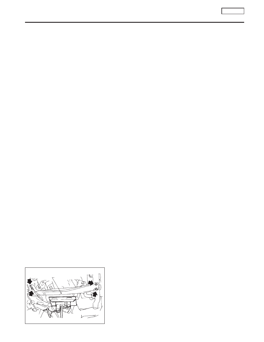
9.
Set a suitable transmission jack under transaxle. Hoist engine
with engine slinger.
10. Remove center member.
SEM092D
Center member
Transmission jack
ENGINE REMOVAL
SR20DE
Components (Cont’d)
EM-107