Nissan Primera P11. Manual - part 411


  Index      Nissan     Nissan Primera P11 (2001 year) - Service and Repair Manual


Search            


Content   ..  409  410  411  412   ..


Nissan Primera P11. Manual - part 411


I

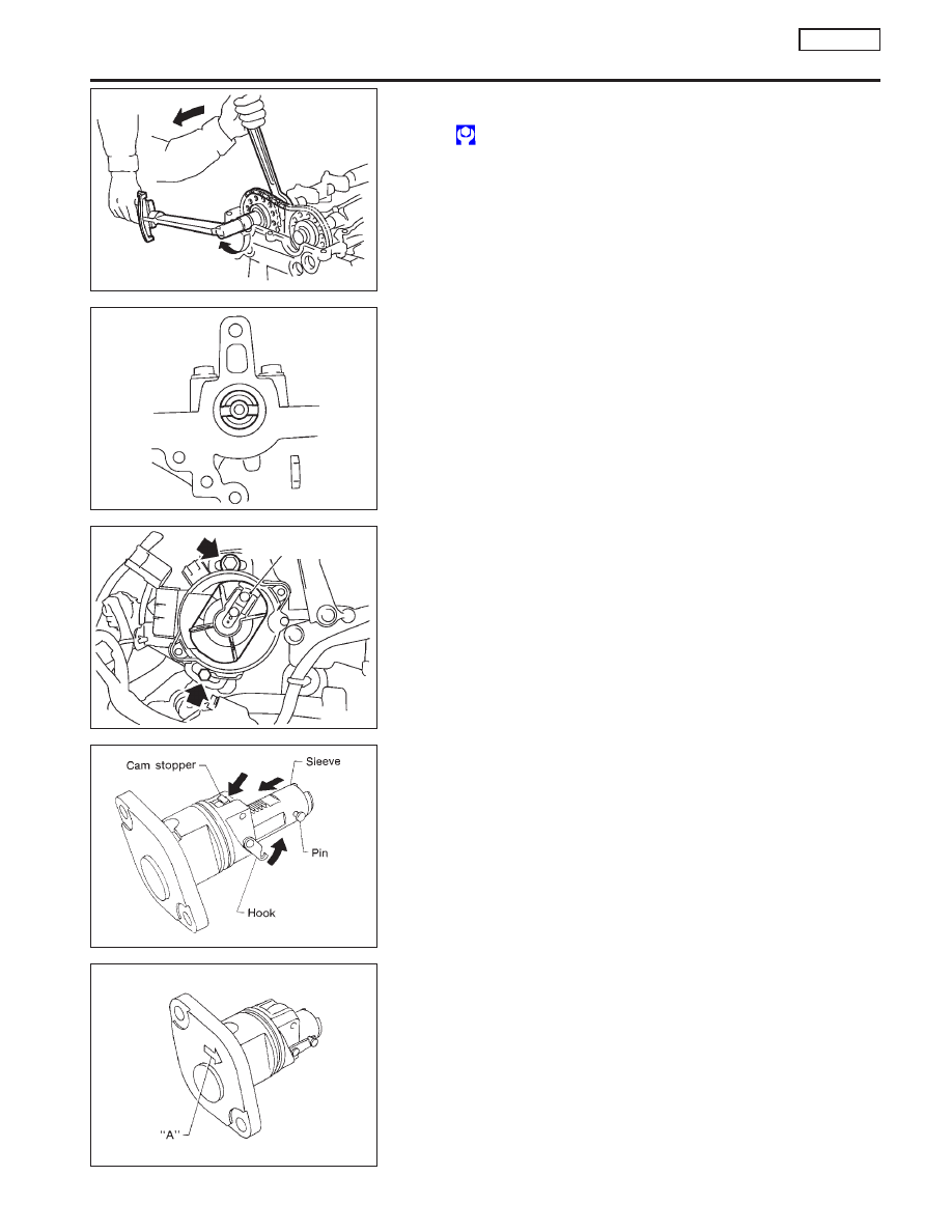
Lock camshafts as shown in figure and tighten to specified
torque.

: 137 - 157 N

m (14.0 - 16.0 kg-m, 101 - 116 ft-lb)

Apply new engine oil to threads and seating surfaces of cam-
shaft sprocket bolts before installing them.

11. Install distributor.

I

Make sure that position of camshaft is as shown in figure.

I

Make sure that No. 1 piston is set at TDC and that distribu-
tor rotor is set at No. 1 cylinder spark position.

12. Install chain tensioner.
Make sure the camshaft sprockets are tightened completely.
Press cam stopper down and “press-in” sleeve until hook can
be engaged on pin. When tensioner is bolted in position the
hook will release automatically. Make sure arrow “A” points
toward engine front.

SEM049G

SEM050G

SEM033G

Rotor head position
(No. 1 cylinder at TDC)

SEM990C

SEM991C

CYLINDER HEAD

SR20DE

Installation (Cont’d)

EM-103

13. Install thermostat housing with water pipe.

14. Install intake manifold supports.

15. Remove old liquid gasket from mating surfaces of rocker cover

and cylinder head.

16. Apply a continuous bead of liquid gasket to rocker cover gas-

ket and cylinder head as shown in the illustrations.

I

Use Genuine RTV silicone sealant Part No. 999MP-A7007
or equivalent.

SEM066G

16 - 20
(1.6 - 2.1, 12 - 15)

6.3 - 8.3
(0.64 - 0.85,
56 - 73)

16 - 20
(1.6 - 2.1, 12 - 15)

16 - 20
(1.6 - 2.1,
12 - 15)

16 - 20
(1.6 - 2.1, 12 - 15)

6.3 - 8.3
(0.64 - 0.85,
56 - 73)

N·m (kg-m, in-lb)

N·m (kg-m, ft-lb)

SEM030G

Intake manifold
supports

BEM006

Engine
front

Unit: mm (in)

3 (0.12)

(0.39)

(0.39)

SEM051G

3 mm
(0.12 in) dia.

CYLINDER HEAD

SR20DE

Installation (Cont’d)

EM-104

17. Install rocker cover and oil separator.

I

Be sure to install washers between bolts and rocker cover.

I

Tightening procedure

STEP 1: Tighten bolts 1 - 10 - 11 - 13 - 8 in that order.
STEP 2: Tighten bolts 1 - 13 in that order.

: 8 - 10 N

m (0.8 - 1.0 kg-m, 69 - 87 in-lb)

18. Install the following parts:

I

Spark plugs and leads

I

Radiator
Refit hoses and refill with coolant.
Refer to MA-29, “Changing Engine Coolant”.

I

Front RH wheel

I

Engine undercovers

19. Connect the following:

I

Vacuum hoses

I

Fuel hoses

I

Wire harnesses and connectors

I

Air duct to intake manifold

I

Front exhaust tube

SEM052G

Engine
front

Tighten in numerical order.

Rocker cover

CYLINDER HEAD

SR20DE

Installation (Cont’d)

EM-105

Components

NEM340

Front engine slinger

Rear insulator

49 - 59
(5.0 - 6.0, 36 - 44)

Rear engine mounting

43 - 55
(4.4 - 5.6,
32 - 41)

43 - 55
(4.4 - 5.6,
32 - 41)

Rear engine slinger

20.6 - 26.5
(2.1 - 2.7, 15 - 20)

20.6 - 26.5
(2.1 - 2.7,
15 - 20)

43 - 55
(4.4 - 5.6,
32 - 41)

55 - 65
(5.6 - 6.6, 41 - 48)

49 - 59 (5.0 - 6.0, 36 - 44)

Front mounting
bracket

Insulator

Center member

77 - 98
(7.9 - 100, 57 - 72)

: N·m (kg-m, ft-lb)

.

43 - 55
(4.4 - 5.6, 32 - 41)

.

49 - 59
(5.0 - 6.0,
36 - 44)

43 - 55
(4.4 - 5.6, 32 - 41)

43 - 55
(4.9 - 5.6, 32 - 41)

49 - 59
(5.0 - 6.0,
36 - 44)

Front engine
mounting

Mounting
bracket

74 - 83 (7.5 - 8.5, 54 - 61)

43 - 55
(4.4 - 5.6, 32 - 41)

64 - 74
(6.5 - 7.5, 47 - 54)

64 - 74
(6.5 - 7.5, 47 - 54)

62 - 78
(6.3 - 8.0, 46 - 58)

64 - 74
(6.5 - 7.5, 47 - 54)

SEC. 112

.

43 - 55
(4.4 - 5.6, 32 - 41)

CVT models

ENGINE REMOVAL

SR20DE

Components

EM-106


Content   ..  409  410  411  412   ..