Nissan Primera P11. Manual - part 410


  Index      Nissan     Nissan Primera P11 (2001 year) - Service and Repair Manual


Search            


Content   ..  408  409  410  411   ..


Nissan Primera P11. Manual - part 410


b.

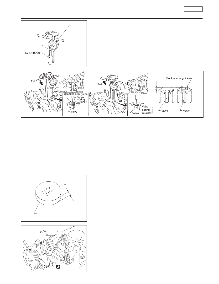
Remove hydraulic lash adjuster.

c.

Install Tool* into hydraulic lash adjuster fixing hole.
* Tool (KV10115700) is screwed into magnetic stand rod used

with dial gauge.

d.

Make sure that the following parts are installed to the cylinder
head: Valve, valve spring, collet, retainer and rocker arm guide
(except shim). Measure difference (T

1

) between sliding surface

of rocker arm guide and valve stem end on shim side.

When measuring, lightly pull dial indicator rod toward you to
eliminate play in Tool (KV10115700).

e.

Select correct shim.

Shim thickness (T):

T

1

± 0.025 mm (0.0010 in)

I

Shims are available in different thicknesses from 2.800 mm
(0.1102 in) to 3.200 mm (0.1260 in) in increments of 0.025 mm
(0.0010 in).

Installation

NLEM0136

1.

Before installing cylinder head gasket, apply liquid gasket as
shown in the illustration.

SEM365DA

Dial gauge

Rod

SEM899D

SEM096D

Shim

Indicate
2.800 mm
(0.1102 in)

AEM250

2.0 - 3.0 mm
(0.079 - 0.118 in)
dia.

Liquid gasket

CYLINDER HEAD

SR20DE

Assembly (Cont’d)

EM-99

2.

Install cylinder head completely with intake and exhaust mani-
folds.

Cylinder head bolts are tightened by plastic zone tightening
method. Whenever the size difference between d1 and d2
exceeds the limit, replace them with new ones.

Limit (d1 − d2):

0.15 mm (0.0059 in)

CAUTION:

If reduction of outer diameter appears in a position other than
d2, use it as d2 point.

3.

Tighten cylinder head bolts using the following procedure.

a.

Tighten all bolts to 39 N

m (4.0 kg-m, 29 ft-lb).

b.

Tighten all bolts to 78 N

m (8.0 kg-m, 58 ft-lb).

c.

Loosen all bolts completely.

d.

Tighten all bolts to 39 N

m (4.0 kg-m, 29 ft-lb).

e.

Method A:
Turn all bolts 90 to 95 degrees clockwise with Tool or
suitable angle wrench.
Method B:
If an angle wrench is not available, mark all cylinder head
bolts on the side facing engine front. Then, turn each cyl-
inder head bolt 90 to 95 degrees clockwise.

f.

Turn all bolts another 90 to 95 degrees clockwise.

g.

Ensure that paint mark on each bolt faces the rear of the
engine. (Method B only)

Do not turn any bolt 180 to 190 degrees clockwise all at once.

SEM390G

SEM877A

Cylinder head bolt washer

Cylinder head side

SEM986C

SEM043G

Method A

degrees

degrees

SEM044G

Method B

degrees

degrees

Engine
front

Paint mark

CYLINDER HEAD

SR20DE

Installation (Cont’d)

EM-100

Tightening torque N

m (kg-m, ft-lb)

a.

39 (4.0, 29)

b.

78 (8.0, 58)

c.

0 (0, 0)

d.

39 (4.0, 29)

e.

90 - 95 degrees (90 degrees preferred)

f.

90 - 95 degrees (90 degrees preferred)

4.

Install cylinder head outside bolts.

5.

Install the following water hoses:

I

Water hose for cylinder block.

I

Water hoses for heater.

6.

Install starter motor.

7.

Remove old liquid gasket from mating surface of LH camshaft
end bracket.

I

Also remove old liquid gasket from mating surface of cyl-
inder head.

8.

Apply liquid gasket to mating surface of LH camshaft end
bracket as shown in illustration.

I

Use Genuine RTV silicone sealant part No. 999MP-A7007
or equivalent.

9.

Install camshafts, camshaft brackets.

I

Position camshaft.

I

LH camshaft key at about 12 o’clock.

I

RH camshaft key at about 10 o’clock.
Apply new engine oil to bearing and cam surfaces of cam-
shafts before installing them.

AEM113

N·m

(kg-m,

ft-lb)

118
(12, 87)

78
(8, 58)

39
(4, 29)

Plastic zone

Elastic zone

SEM037G

Water outlet

Water inlet

SEM036G

BEM004

Apply liquid gasket to the
shaded area.

LH camshaft end bracket

SEM045G

RH camshaft key

LH camshaft key

CYLINDER HEAD

SR20DE

Installation (Cont’d)

EM-101

I

Position camshaft brackets as shown in the illustration.
Apply new engine oil to threads and seating surfaces of
camshaft bracket bolts before installing them.

I

Arrange bolts (Size and length).
A: M6 x 53.8 mm (2.12 in)
B: M6 x 37 mm (1.46 in)
C: M8 x 35 mm (1.38 in)

I

Tightening procedure

STEP 1:

RH camshaft

Tighten bolts 9 - 10 in that order then tighten
bolts 1 - 8 in numerical order.

: 2 N

m (0.2 kg-m, 17 in-lb)

LH camshaft

Tighten bolts 11 - 12 in that order then tighten
bolts 1 - 10 in numerical order.

: 2 N

m (0.2 kg-m, 17 in-lb)

STEP 2:

Tighten bolts in numerical order.

: 6 N

m (0.6 kg-m, 52 in-lb)

STEP 3:

Tighten bolts in numerical order.
Bolt type A B

: 9.8 - 11.8 N

m (1.0 - 1.2 kg-m, 7.2 - 8.7 ft-lb)

Bolt type C

: 18 - 25 N

m (1.8 - 2.6 kg-m, 13 - 19 ft-lb)

10. Install camshaft sprockets and timing chain on them.

Line up mating marks on timing chain with mating marks
on camshaft sprockets.

SEM098DA

RH camshaft
bracket

End bracket

End bracket

Engine
front

No. 1 to 4
brackets

No. 1 to 4 brackets

LH camshaft
bracket

SEM046G

Engine
front

Bolt type

SEM047G

Engine
front

RH camshaft

LH camshaft

Tighten in numerical order.

SEM046G

Engine
front

Bolt type

SEM048G

Mating mark

Mating mark

.

RH camshaft sprocket

.

LH camshaft sprocket

Mating mark

Mating mark

CYLINDER HEAD

SR20DE

Installation (Cont’d)

EM-102


Content   ..  408  409  410  411   ..