Nissan Primera P11. Manual - part 331
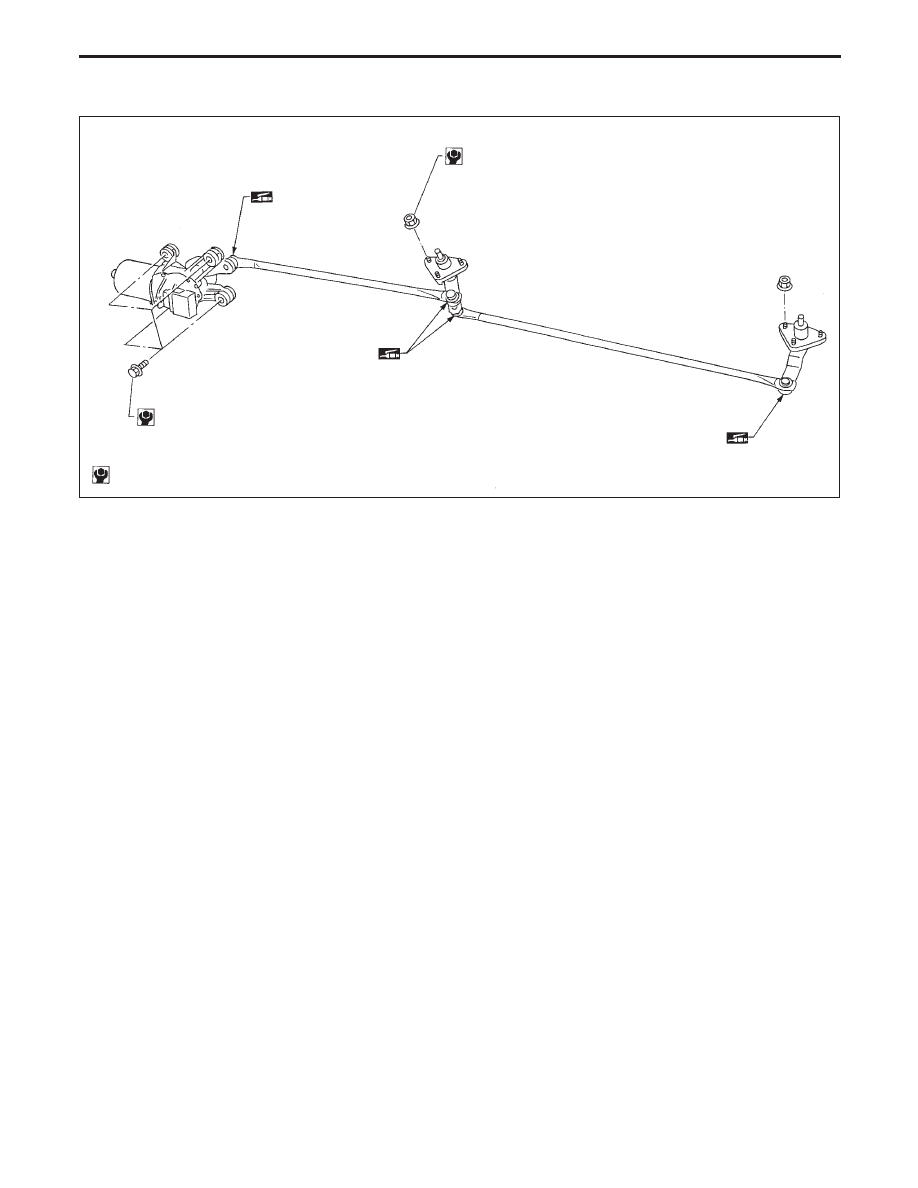
WIPER LINKAGE
* Structure is basically the opposite for RHD models.
Removal
1. Remove 4 bolts that secure wiper motor.
2. Detach wiper motor from wiper linkage at ball joint.
3. Remove wiper linkage.
Be careful not to break ball joint rubber boot.
Installation
●
Grease ball joint area before installation.
1. Installation is the reverse order of removal.
MEL664DA
LHD models*
3.8 - 5.1 (0.39 - 0.52, 33.9 - 45.1)
3.8 - 5.1 (0.39 - 0.52, 33.9 - 45.1)
: N·m (kg-m, in-lb)
FRONT WIPER AND WASHER
Removal and Installation (Cont’d)
EL-191