Nissan Primera P11. Manual - part 329


  Index      Nissan     Nissan Primera P11 (2001 year) - Service and Repair Manual


Search            


Content   ..  327  328  329  330   ..


Nissan Primera P11. Manual - part 329


Trouble Diagnoses

SYMPTOM CHART

REFERENCE PAGE

EL-183

EL-184

EL-184

EL-185

SYMPTOM

POWER

SUPPL

Y

A

ND

GROUND

CIRCUIT

CHECK

DIAGNOSTIC

PROCEDURE

1

(Lighting

switch

input

signal

check)

DIAGNOSTIC

PROCEDURE

2

(Key

switch

input

signal

check)

DIAGNOSTIC

PROCEDURE

3

Light warning chime does not acti-
vate.

X

X

X

Ignition key warning chime does
not activate.

X

X

X

All warning chimes do not activate.

X

X

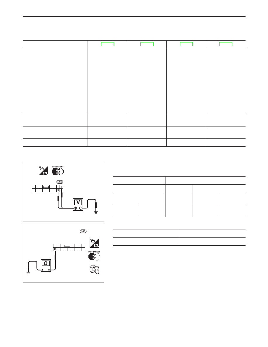
POWER SUPPLY AND GROUND CIRCUIT CHECK

Power Supply Circuit Check

Terminals

Ignition switch position

OFF

ACC

ON

9

Ground

Battery
voltage

Battery
voltage

Battery
voltage

1

Ground

0V

0V

Battery
voltage

Ground Circuit Check

Terminals

Continuity

16

- Ground

Yes

Time control
unit connector

YEL430B

Time control unit connector

YEL431B

WARNING CHIME

EL-183

DIAGNOSTIC PROCEDURE 1

(Lighting switch input signal check)

CHECK LIGHTING SWITCH INPUT
SIGNAL.
Check voltage between control unit
terminal

10

and ground.

OK

NG

Check the following.

15A fuse (No. 34 ,
located in the fuse and
fusible link box)

Harness for open or
short between control
unit and lighting switch

Go to Procedure 3.

Condition of lighting

switch

Voltage [V]

1ST or 2ND

Approx. 12

OFF

0

DIAGNOSTIC PROCEDURE 2

(Key switch input signal check)

CHECK KEY SWITCH INPUT SIGNAL.
Check voltage between control unit
terminal

22

and ground.

OK

NG

Check the following.

Key switch
Refer to “Electrical
Components Inspec-
tion” (EL-185).

10A fuse [No. 16 ,
located in fuse block
(J/B)]

Harness for open or
short between key
switch and fuse

Harness for open or
short between control
unit and key switch

Go to Procedure 3.

Condition of key switch

Voltage [V]

Key is inserted.

Approx. 12

Key is withdrawn.

0

YEL432B

Time control
unit connector

YEL433B

Time control
unit connector

: Approx.

12V

: 0V

WARNING CHIME

Trouble Diagnoses (Cont’d)

EL-184

DIAGNOSTIC PROCEDURE 3

CHECK DOOR SWITCH INPUT SIG-
NAL.
Check voltage between fuse block (J/B)
terminal

16J

and ground.

OK

NG

Check the following.

Driver side door switch
Refer to “Electrical
Components Inspec-
tion” (EL-185).

Door switch ground
circuit

Harness for open or
short between control
unit and door switch

Check continuity between fuse block
(J/B) terminal

16J

and control unit ter-

minal

6

.

Continuity should exist.

OK

NG

Replace fuse block (J/B).

Replace time control unit.

Condition of driver’s door

Voltage [V]

Driver side door is closed.

Approx. 12

Driver side door is open.

0

Electrical Components Inspection

KEY SWITCH (insert)

Check continuity between terminals when key is inserted in igni-
tion key cylinder and key is removed from ignition key cylinder.

Terminal No.

Condition

Continuity

1

-

2

Key is inserted.

Yes

Key is removed.

No

DRIVER SIDE DOOR SWITCH

Check continuity between terminals when door switch is pushed
and released.

Terminal No.

Condition

Continuity

2

-

3

(Type-1) or

1

- Ground (Type-2)

Door switch is pushed.

No

Door switch is
released.

Yes

YEL434B

Fuse block (J/B) connector

YEL435B

Time control unit
connector

Fuse block (J/B)
connector

YEL436B

Key switch connector

YEL026D

YEL025D

WARNING CHIME

Trouble Diagnoses (Cont’d)

EL-185

System Description

WIPER OPERATION

The wiper switch is controlled by a lever built into the combination switch.
There are three wiper switch positions:

LO speed

HI speed

INT (Intermittent).

With the ignition switch in the ON or START position, power is supplied

through 20A fuse (No.

located in the fuse block)

to wiper motor terminal

6

and

3

.

Low and high speed wiper operation

Ground is supplied to wiper switch terminal

17

through body grounds

E11

and

E37

.

When the wiper switch is placed in the LO position, ground is supplied

Through terminal

14

of the wiper switch

to wiper motor terminal

2

.

With power and ground supplied, the wiper motor operates at low speed.
When the wiper switch is placed in the HI position, ground is supplied

Through terminal

16

of the wiper switch

to wiper motor terminal

1

.

With power and ground supplied, the wiper motor operates at high speed.

Auto stop operation

With wiper switch turned OFF, wiper motor will continue to operate until wiper arms reach windshield base.
When wiper arms are not located at base of windshield with wiper switch OFF, ground is provided

from terminal

14

of the wiper switch

to wiper motor terminal

2

, in order to continue wiper motor operation at low speed.

Ground is also supplied

through terminal

13

of the wiper switch

to front wiper relay terminal

3

through terminal

4

of the front wiper relay

to wiper motor terminal

5

through terminal

4

of the wiper motor, and

through body grounds

E11

and

E37

.

When wiper arms reach base of windshield, wiper motor terminals

5

and

3

are connected instead of

terminals

5

and

4

. Wiper motor will then stop wiper arms at the PARK position.

Intermittent operation

With variable intermittent
The wiper motor operates the wiper arms at a set interval of approximately 2 to 20 seconds. This feature is
controlled by the combination switch wiper amplifier.
When the wiper switch is placed in the INT position, ground is supplied

to front wiper relay terminal

5

from wiper switch terminal

13

through body grounds

E37

and

E11

.

to wiper motor terminal

2

through the wiper switch terminal

14

to wiper switch terminal

13

through front wiper relay terminal

3

The desired interval time is input

to front wiper relay terminal

1

from wiper switch terminal

20

.

The wiper motor operates at low speed at the desired time interval.

FRONT WIPER AND WASHER

EL-186


Content   ..  327  328  329  330   ..