Nissan Primera P11. Manual - part 281
Diagnostic Procedure
=NCEC0454
1
INSPECTION START
Do you have CONSULT-II?
Yes or No
Yes
©
GO TO 2.
No
©
GO TO 3.
2
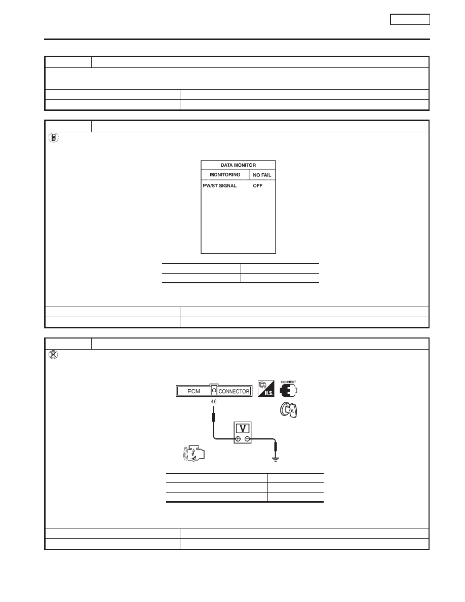
CHECK OVERALL FUNCTION
With CONSULT-II
1. Start engine.
2. Check “PW/ST SIGNAL” in “DATA MONITOR” mode with CONSULT-II under the following conditions.
PEF591I
MTBL0141
OK or NG
OK
©
INSPECTION END
NG
©
GO TO 4.
3
CHECK OVERALL FUNCTION
Without CONSULT-II
1. Start engine.
2. Check voltage between ECM terminal 46 and ground under the following conditions.
SEF148X
MTBL0142
OK or NG
OK
©
INSPECTION END
NG
©
GO TO 4.
Steering is in neutral position
OFF
Steering is turned
ON
Condition
Voltage
When steering wheel is turned quickly
Approximately 0V
Except above
Approximately 5V
CONNECT
POWER STEERING OIL PRESSURE SWITCH
SR20DE
Diagnostic Procedure
EC-323