Nissan Primera P11. Manual - part 280


  Index      Nissan     Nissan Primera P11 (2001 year) - Service and Repair Manual


Search            


Content   ..  278  279  280  281   ..


Nissan Primera P11. Manual - part 280


3

DETECT MALFUNCTIONING PART

Check the following.

I

15A fuse

I

Harness for open or short between fuse and fuel pump relay

©

Repair harness or connectors.

4

CHECK POWER GROUND CIRCUIT

1. Turn ignition switch “OFF”.
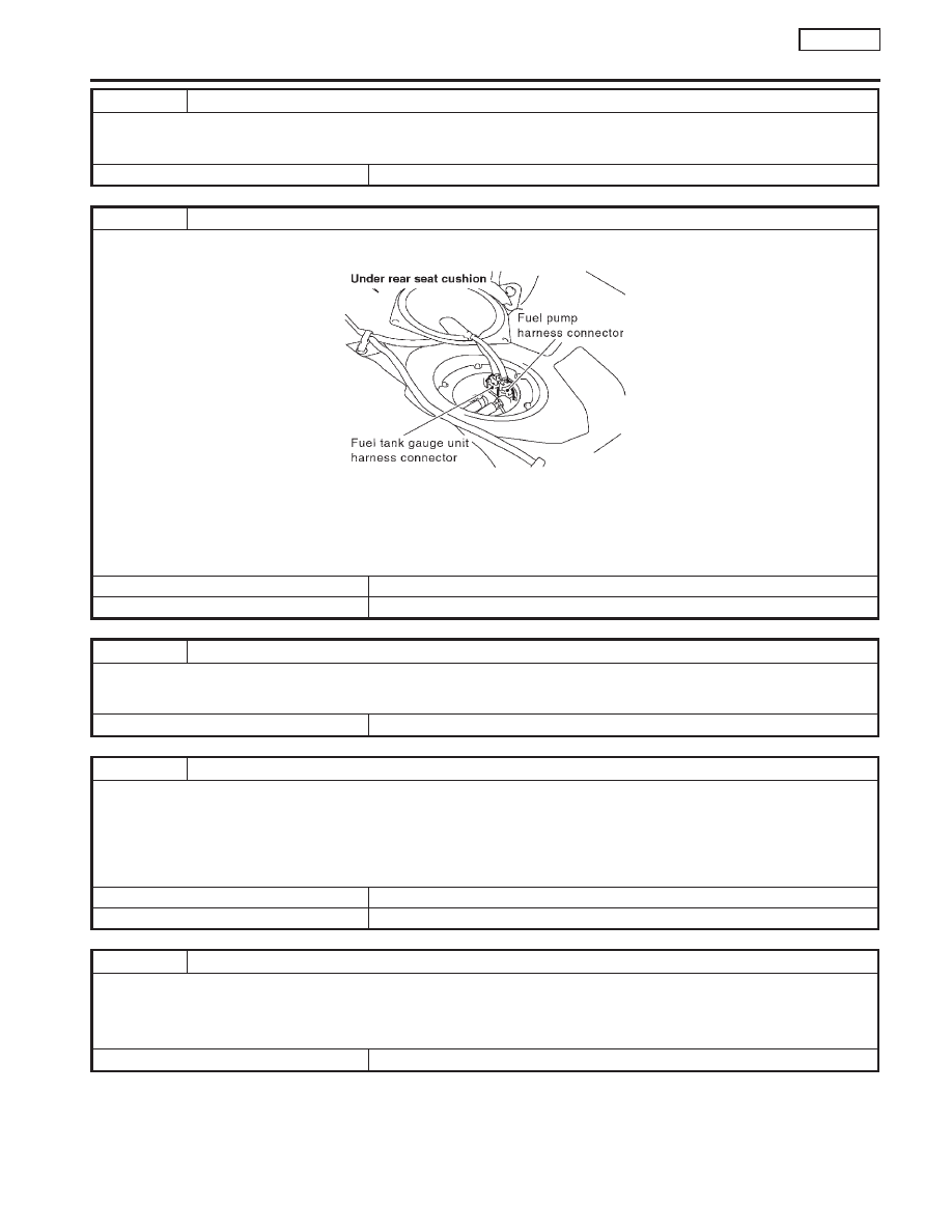
2. Disconnect fuel pump harness connector.

SEF299W

3. Check harness continuity between fuel pump harness connector terminal 2 and body ground, terminal 1 and fuel pump relay connector

terminal 9J.
Refer to wiring diagram.

Continuity should exist.

4. Also check harness for short to ground and short to power.

OK or NG

OK

©

GO TO 6.

NG

©

GO TO 5.

5

DETECT MALFUNCTIONING PART

Check the following.

I

Harness for open or short between fuel pump and body ground

I

Harness for open or short between fuel pump and fuel pump relay

©

Repair open circuit or short to ground or short to power in harness or connectors.

6

CHECK OUTPUT SIGNAL CIRCUIT

1. Disconnect ECM harness connector.
2. Check harness continuity between ECM terminal 21 and fuel pump relay connector terminal 19C.

Refer to wiring diagram.

Continuity should exist.

3. Also check harness for short to ground and short to power.

OK or NG

OK

©

GO TO 8.

NG

©

GO TO 7.

7

DETECT MALFUNCTIONING PART

Check the following.

I

Harness connectors M50, F104 (CVT: M81, F115)

I

Harness for open or short between ECM and fuel pump relay

NG

©

Repair open circuit or short to ground or short to power in harness or connectors.

FUEL PUMP

SR20DE

Diagnostic Procedure (Cont’d)

EC-319

Component Inspection

NCEC0449

FUEL PUMP RELAY

NCEC0449S01

Check continuity between terminals 3 and 5.

Conditions

Continuity

12V direct current supply between terminals 1 and 2

Yes

No current supply

No

If NG, replace relay.

FUEL PUMP

NCEC0449S02

1.

Disconnect fuel pump harness connector.

2.

Check resistance between terminals 1 and 2.

Resistance: 0.2 - 5.0

[at 25°C (77°F)]

If NG, replace fuel pump.

8

CHECK FUEL PUMP RELAY

Refer to “Component Inspection”, EC-SR-320.

OK or NG

OK

©

GO TO 9.

NG

©

Replace fuel pump relay.

9

CHECK FUEL PUMP

Refer to “Component Inspection”, EC-SR-320.

OK or NG

OK

©

GO TO 10.

NG

©

Replace fuel pump.

10

CHECK INTERMITTENT INCIDENT

Perform “TROUBLE DIAGNOSIS FOR INTERMITTENT INCIDENT”, EC-SR-114.

©

INSPECTION END

SEF145X

SEF326W

FUEL PUMP

SR20DE

Component Inspection

EC-320

Component Description

NCEC0451

The power steering oil pressure switch is attached to the power
steering high-pressure tube and detects a power steering load.
When a power steering load is detected, it signals the ECM. The
ECM adjusts the IACV-AAC valve to increase the idle speed and
adjust for the increased load.

CONSULT-II Reference Value in Data Monitor
Mode

NCEC0452

Specification data are reference values.

MONITOR ITEM

CONDITION

SPECIFICATION

PW/ST SIGNAL

I

Engine: After warming up, idle
the engine

Steering wheel in neutral position
(forward direction)

OFF

The steering wheel is fully turned

ON

ECM Terminals and Reference Value

NCEC0453

Specification data are reference values and are measured between each terminal and 48 (ECM ground).

TERMI-

NAL

NO.

WIRE

COLOR

ITEM

CONDITION

DATA (DC Voltage)

46

PU/W

Power steering oil pressure
switch

[Engine is running]

I

Steering wheel is fully turned

Approximately 0V

[Engine is running]

I

Steering wheel is not turned

Approximately 5V

NEF124A

Power steering oil pressure switch

POWER STEERING OIL PRESSURE SWITCH

SR20DE

Component Description

EC-321

Wiring Diagram

NCEC0450

YEC254

POWER STEERING OIL PRESSURE SWITCH

SR20DE

Wiring Diagram

EC-322


Content   ..  278  279  280  281   ..