Nissan Primera P11. Manual - part 275
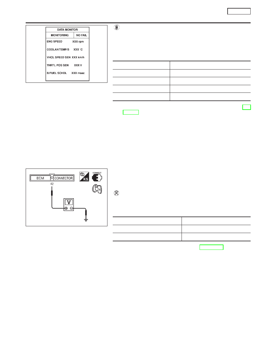
With CONSULT-II
1)
Turn ignition switch “ON”.
2)
Select “DATA MONITOR” mode with CONSULT-II.
3)
Start engine and warm it up to normal operating temperature.
4)
Maintain the following conditions for at least 50 consecutive
seconds.
ENG SPEED
1,500 - 3,400 rpm
COOLAN TEMP/S
More than 70°C (158°F)
B/FUEL SCHDL
2.4 - 12.0 msec
VHCL SPEED SE
64 - 130 km/h (40 - 81 MPH)
Selector lever
Suitable position
5)
If 1st trip DTC is detected, go to “Diagnostic Procedure”, EC-
SR-301.
Overall Function Check
NCEC0429
Use this procedure to check the overall function of the park/neutral
position switch circuit. During this check, a 1st trip DTC might not
be confirmed.
Without CONSULT-II
1)
Turn ignition switch “ON”.
2)
Check voltage between ECM terminal 42 (PNP switch signal)
and body ground under the following conditions.
Condition (Gear position)
Voltage (V) (Known good data)
“P” (CVT only) and “N” position
Approx. 0
Except the above position
BATTERY VOLTAGE (11 - 14V)
3)
If NG, go to “Diagnostic Procedure”, EC-SR-301.
NEF118A
SEF137X
DTC P1706 PARK/NEUTRAL POSITION (PNP) SWITCH
SR20DE
DTC Confirmation Procedure (Cont’d)
EC-299