Nissan Primera P11. Manual - part 274
System Description
NCEC0560
The malfunction information related to CVT is transferred through the line (circuit) from TCM (Transmission
Control Module) to ECM. Therefore, be sure to erase the malfunction information such as DTC not only in TCM
(Transmission Control Module) but also ECM after the CVT related repair.
ECM Terminals and Reference Value
NCEC0561
Specification data are reference values and are measured between each terminal and 48 (ECM ground).
TER-
MINAL
NO.
WIRE
COLOR
ITEM
CONDITION
DATA (DC Voltage)
91
PU/Y
CVT check signal
[Ignition switch “ON”]
[Engine is running]
0 - Approximately 5V
On Board Diagnosis Logic
NCEC0562
DTC No.
Malfunction is detected when ...
Check Items (Possible Cause)
P1605
1605
I
An incorrect signal from TCM (Transmission Control
Module) is sent to ECM.
I
Harness or connectors
[The communication line circuit between ECM and
TCM (Transmission Control Module) is open or
shorted.]
I
Dead (Weak) battery
I
TCM (Transmission Control Module)
DTC Confirmation Procedure
NCEC0563
NOTE:
If “DTC CONFIRMATION PROCEDURE” has been previously
conducted, always turn ignition switch “OFF” and wait at least 9
seconds before conducting the next test.
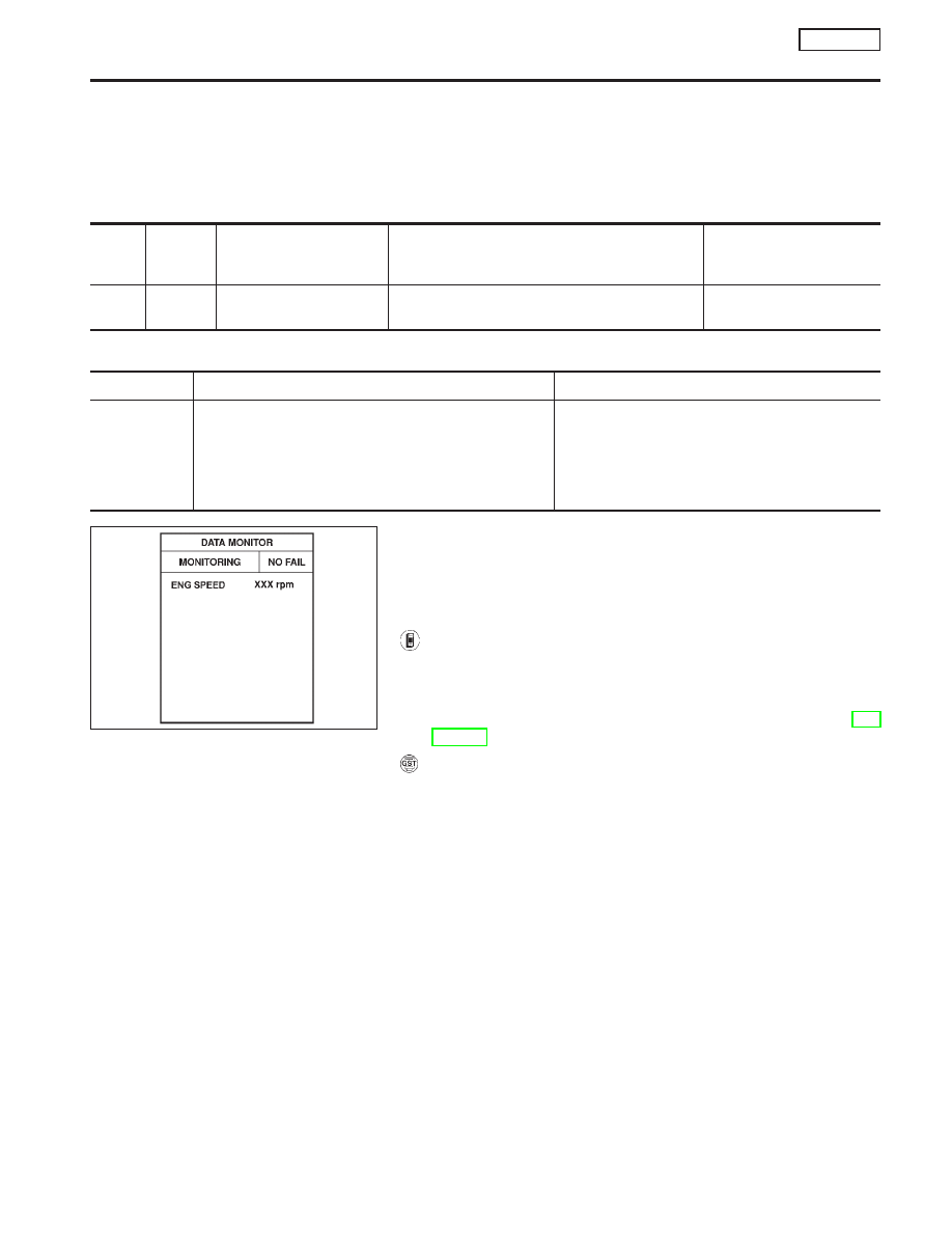
With CONSULT-II
1)
Turn ignition switch “ON”.
2)
Select “DATA MONITOR” mode with CONSULT-II.
3)
Start engine and let it idle for at least 40 seconds.
4)
If 1st trip DTC is detected, go to “Diagnostic Procedure”, EC-
SR-297.
With GST
Follow the procedure “With CONSULT-II” above.
NEF068A
DTC P1605 A/T DIAGNOSIS COMMUNICATION LINE
SR20DE
System Description
EC-295