Nissan Primera P11. Manual - part 251
Wiring Diagram
NCEC0177
YEC086A
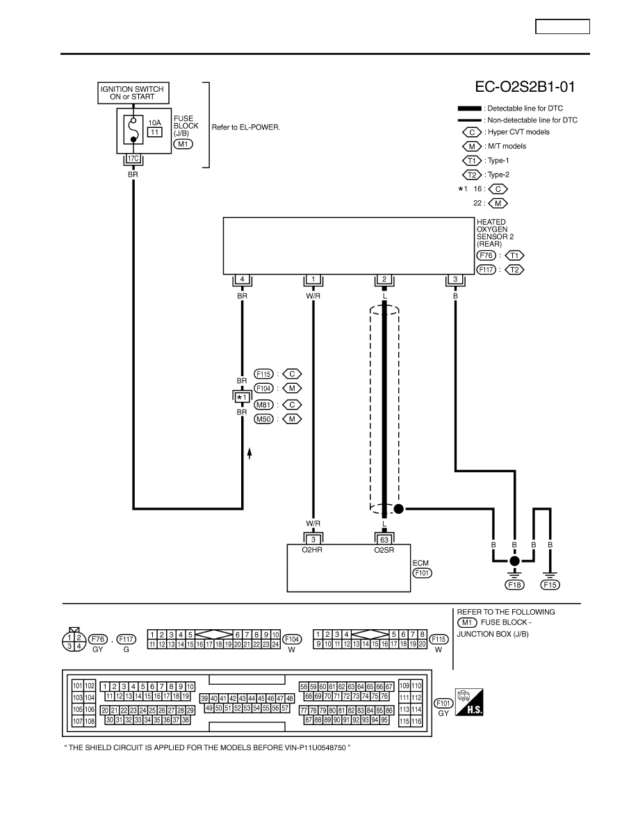
DTC P0140 HEATED OXYGEN SENSOR 2
(REAR) (HIGH VOLTAGE)
SR20DE
Wiring Diagram
EC-203
|
|
|
Wiring Diagram NCEC0177 YEC086A DTC P0140 HEATED OXYGEN SENSOR 2 (REAR) (HIGH VOLTAGE) SR20DE Wiring Diagram EC-203 |