Nissan Primera P11. Manual - part 234
Diagnostic Procedure
NCEC0077
1
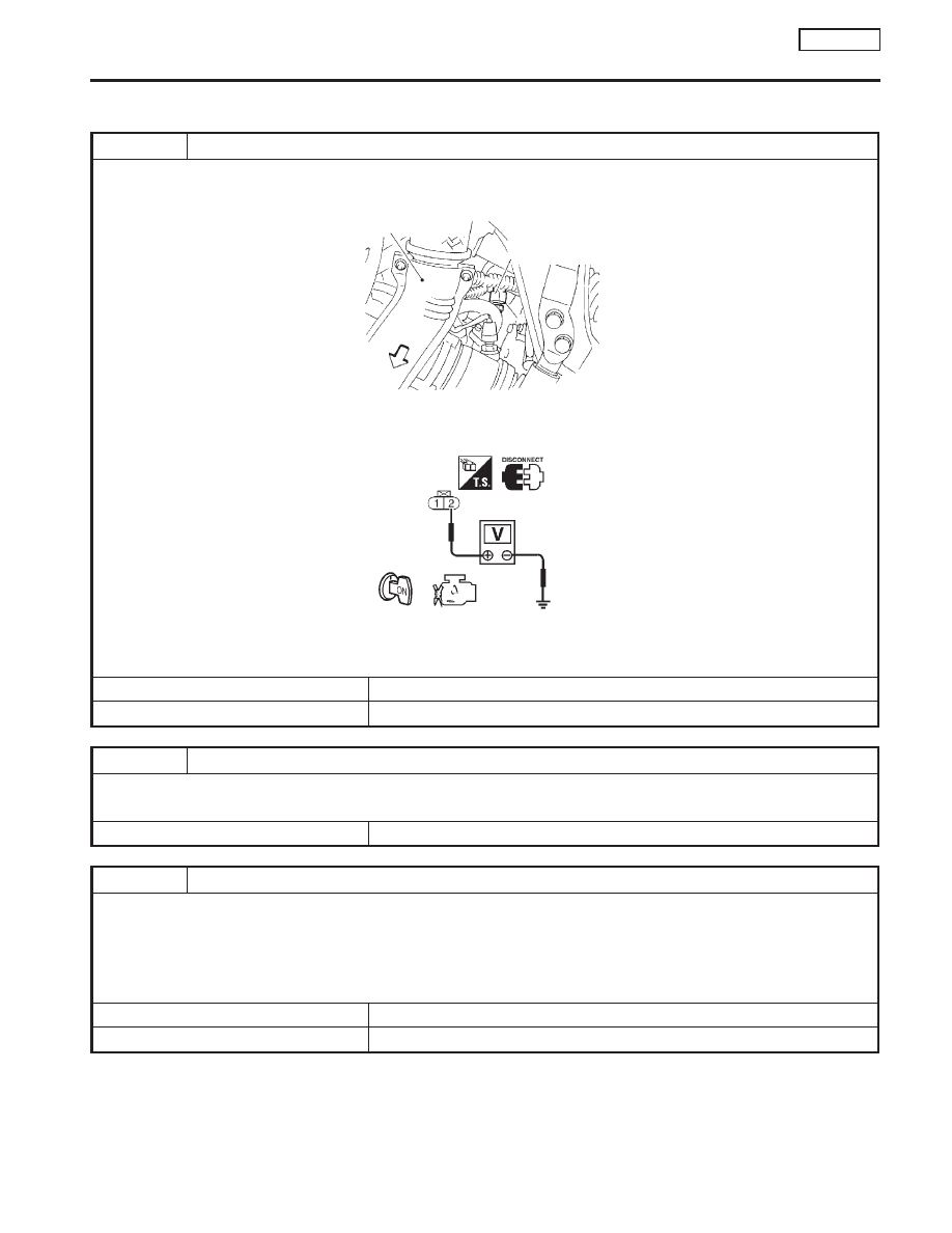
CHECK POWER SUPPLY
1. Turn ignition switch “OFF”.
2. Disconnect engine coolant temperature sensor harness connector.
SEF205X
3. Turn ignition switch “ON”.
4. Check voltage between terminal 2 and ground with CONSULT-II or tester.
SEF997W
Voltage: Approximately 5V
OK or NG
OK
©
GO TO 3.
NG
©
GO TO 2.
2
DETECT MALFUNCTIONING PART
Check the harness for open or short between ECM and engine coolant temperature sensor.
©
Repair harness or connectors.
3
CHECK GROUND CIRCUIT
1. Turn ignition switch “OFF”.
2. Check harness continuity between engine coolant temperature sensor harness connector terminal 1 and engine ground.
Refer to wiring diagram.
Continuity should exist.
3. Also check harness for short to ground and short to power.
OK or NG
OK
©
GO TO 5.
NG
©
GO TO 4.
Front exhaust tube
Front
Coolant temperature
sensor harness
connector
DTC P0115 ENGINE COOLANT TEMPERATURE SENSOR
(ECTS) (CIRCUIT)
SR20DE
Diagnostic Procedure
EC-135