Nissan Primera P11. Manual - part 235
With CONSULT-II
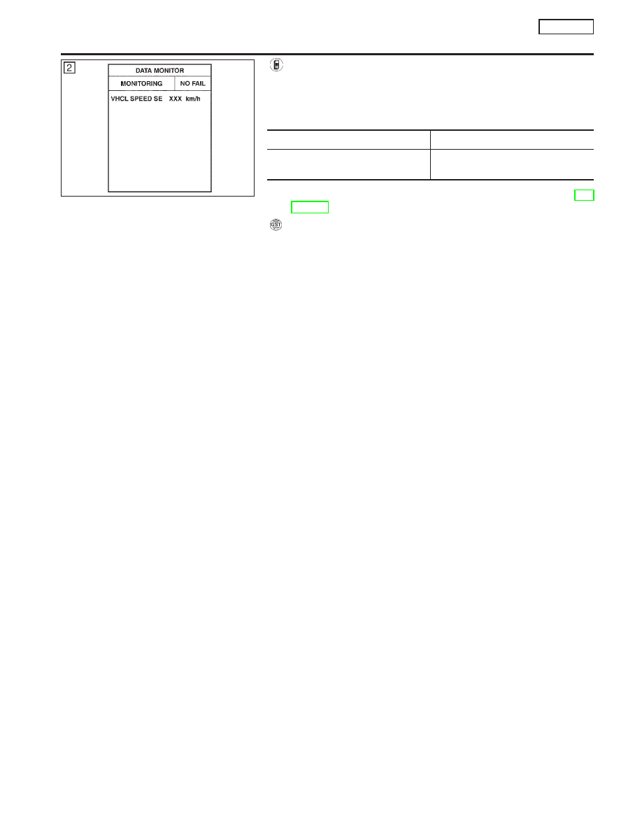
1)
Turn ignition switch “ON” and select “DATA MONITOR” mode
with CONSULT-II.
2)
Start engine and maintain the following conditions for at least
5 consecutive seconds.
VHCL SPEED SE
More than 4 km/h (2 MPH)
Selector lever
Suitable position except “P” or “N”
position
3)
If 1st trip DTC is detected, go to “Diagnostic Procedure”, EC-
SR-141.
With GST
Follow the procedure “With CONSULT-II” above.
PEF651U
DTC P0120 THROTTLE POSITION SENSOR
SR20DE
DTC Confirmation Procedure (Cont’d)
EC-139