Nissan Primera P11. Manual - part 226
ECM Terminals and Reference Value
NCEC0044
PREPARATION
NCEC0044S01
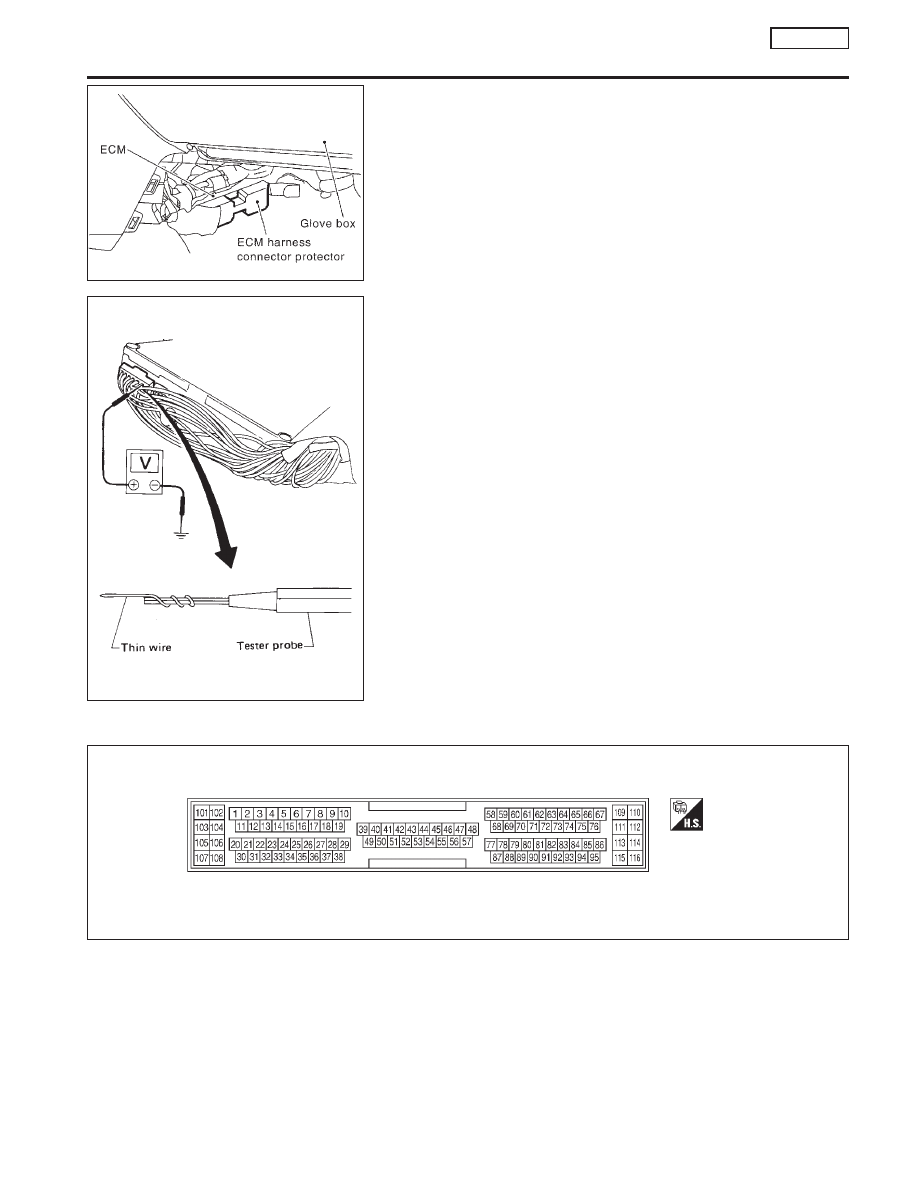
1.
ECM is located behind the center console. For this inspection:
Remove the front passenger center console panel.
2.
Remove ECM harness protector.
3.
Perform all voltage measurements with the connector con-
nected. Extend tester probe as shown to perform tests easily.
I
Open harness securing clip to make testing easier.
I
Use extreme care not to touch 2 pins at one time.
I
Data is for comparison and may not be exact.
ECM HARNESS CONNECTOR TERMINAL LAYOUT
NCEC0044S02
ECM INSPECTION TABLE
NCEC0044S03
Specification data are reference values and are measured between
each terminal and 48 (ECM ground).
SEF967W
SEF367I
SEF970W
TROUBLE DIAGNOSIS — GENERAL DESCRIPTION
SR20DE
ECM Terminals and Reference Value
EC-103