Nissan Primera P11. Manual - part 224
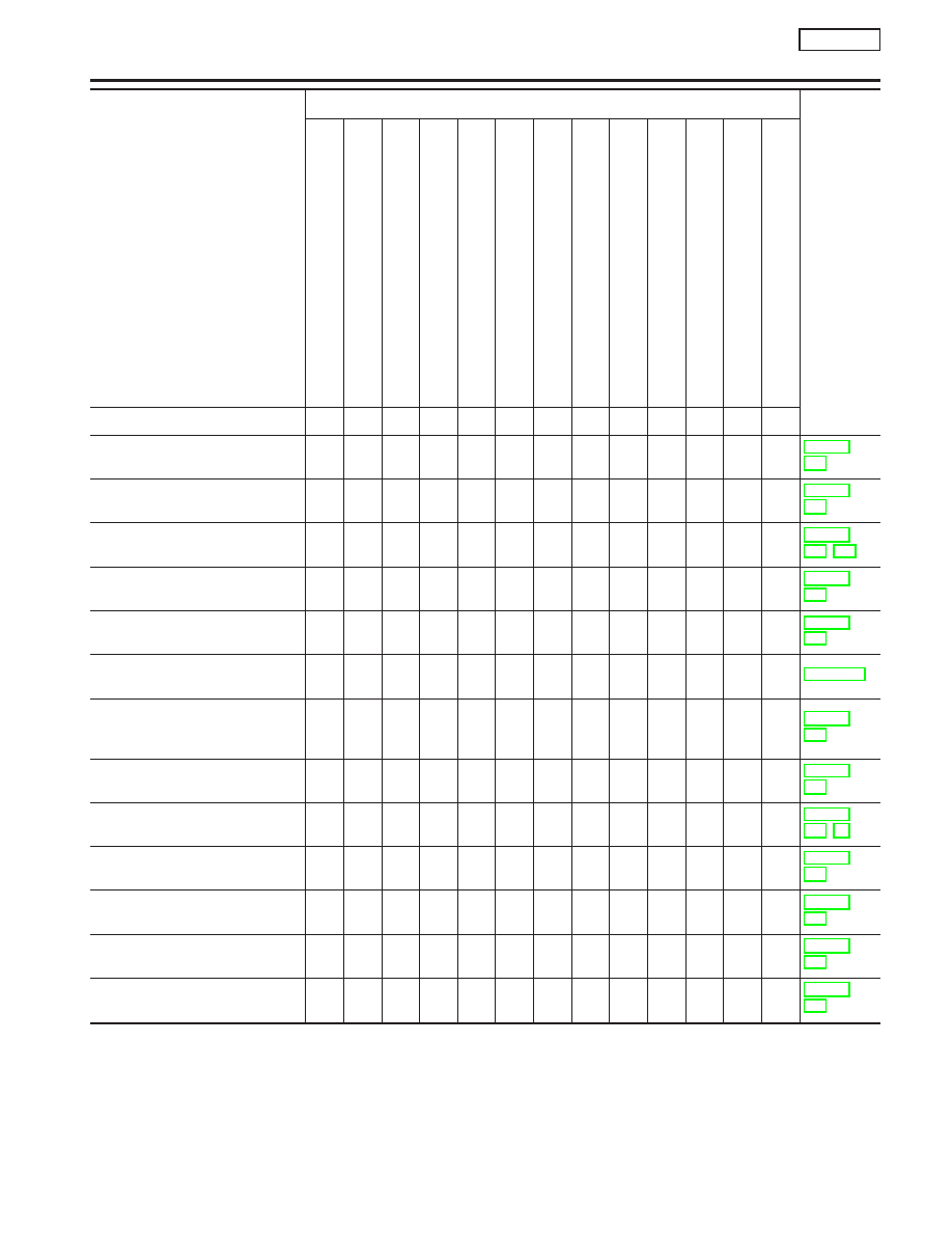
SYMPTOM
Reference
page
HARD/NO
ST
AR
T/REST
AR
T
(EXCP
.
HA)
ENGINE
ST
ALL
HESIT
A
TION/SURGING/FLA
T
SPOT
SP
ARK
KNOCK/DET
ONA
TION
LACK
OF
POWER/POOR
ACCELERA
TION
HIGH
IDLE/LOW
IDLE
ROUGH
IDLE/HUNTING
IDLING
VIBRA
TION
SLOW/NO
RETURN
T
O
IDLE
OVERHEA
TS/W
A
TER
TEMPERA
TURE
HIGH
EXCESSIVE
FUEL
CONSUMPTION
EXCESSIVE
OIL
CONSUMPTION
BA
TTER
Y
DEAD
(UNDER
CHARGE)
Warranty symptom code
AA
AB
AC
AD
AE
AF
AG
AH
AJ
AK
AL
AM
HA
Camshaft position sensor circuit
2
2
3
3
3
3
3
3
Mass air flow sensor circuit
1
1
2
2
2
2
2
2
Heated oxygen sensor 1 (front)
circuit
1
2
3
2
2
2
2
Engine coolant temperature sen-
sor circuit
1
1
2
3
2
3
2
2
3
2
Throttle position sensor circuit
1
2
2
2
2
2
2
2
Incorrect throttle position sensor
adjustment
3
1
1
1
1
1
1
1
Vehicle speed sensor circuit or
ABS actuator and electric unit
(control unit) circuit
2
3
3
3
Knock sensor circuit
2
3
ECM
2
2
3
3
3
3
3
3
3
3
3
Start signal circuit
2
PNP switch circuit
3
3
3
3
3
Power steering oil pressure
switch circuit
2
3
3
Electrical load signal circuit
3
3
1 - 6: The numbers refer to the order of inspection.
(continued on next page)
TROUBLE DIAGNOSIS — GENERAL DESCRIPTION
SR20DE
Symptom Matrix Chart (Cont’d)
EC-95