Nissan Primera P11. Manual - part 225
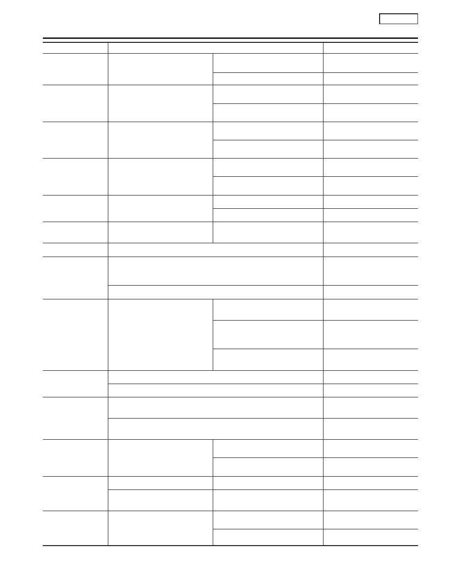
MONITOR ITEM
CONDITION
SPECIFICATION
LOAD SIGNAL
I
Engine: running
Rear window defogger or headlamp
“ON”
ON
Except the above
OFF
B/FUEL SCHDL
I
Engine: After warming up
I
Air conditioner switch: OFF
I
Shift lever: “N”
I
No-load
Idle
2.4 - 3.2 msec
2,000 rpm
1.4 - 2.8 msec
IGN TIMING
I
Engine: After warming up
I
Air conditioner switch: OFF
I
Shift lever: “N”
I
No-load
Idle
15° BTDC
2,000 rpm
Approx. 40° BTDC
IACV-AAC/V
I
Engine: After warming up
I
Air conditioner switch: OFF
I
Shift lever: “N”
I
No-load
Idle
5 - 20 steps
2,000 rpm
—
PURG VOL C/V
I
Engine: Running
Vehicle stopped
0%
Vehicle running
—
A/F ALPHA -B1
I
Engine: After warming up
Maintaining engine speed at 2,000
rpm
53 - 155%
AIR COND RLY
I
Air conditioner switch: OFF
,
ON
OFF
,
ON
FUEL PUMP RLY
I
Ignition switch is turned to ON (Operates for 2 seconds)
I
Engine running and cranking
I
When engine is stopped (stops in 1.5 seconds)
ON
I
Except as shown above
OFF
COOLING FAN
I
After warming up engine, idle the
engine.
I
Air conditioner switch: OFF
Engine coolant temperature is 94°C
(201°F) or less
OFF
Engine coolant temperature is
between 95°C (203°F) and 104°C
(219°F).
LOW
Engine coolant temperature is 105°C
(221°F) or more
HIGH
HO2S1 HTR (B1)
I
Engine speed: Below 3,200 rpm
ON
I
More than 20 seconds after exceeding 3,200 rpm
OFF
HO2S2 HTR (B1)
I
Engine speed: Below 3,600 rpm [After driving for 2 minutes at a speed
of 70 km/h (43 MPH) or more]
ON
I
Engine speed: Above 3,600 rpm
I
Ignition switch ON (Engine stopped)
OFF
CAL/LD VALUE
I
Engine: After warming up
I
Air conditioner switch: OFF
I
Shift lever: “N”
I
No-load
Idle
Not used
2,500 rpm
Not used
ABSOL TH
⋅
P/S
I
Engine: Idle
Throttle valve fully closed
0.0°
I
Ignition switch: ON
(Engine stopped)
Throttle valve fully opened
Approx. 80°
MASS AIRFLOW
I
Engine: After warming up
I
Air conditioner switch: OFF
I
Shift lever: N
I
No-load
Idle
2.5 - 5.0 g
⋅
m/s
2,500 rpm
7.1 - 12.5 g
⋅
m/s
TROUBLE DIAGNOSIS — GENERAL DESCRIPTION
SR20DE
CONSULT-II Reference Value in Data Monitor Mode (Cont’d)
EC-99