Nissan Primera P11. Manual - part 198


  Index      Nissan     Nissan Primera P11 (2001 year) - Service and Repair Manual


Search            


Content   ..  196  197  198  199   ..


Nissan Primera P11. Manual - part 198


Diagnostic Procedure

NLEC0590

1

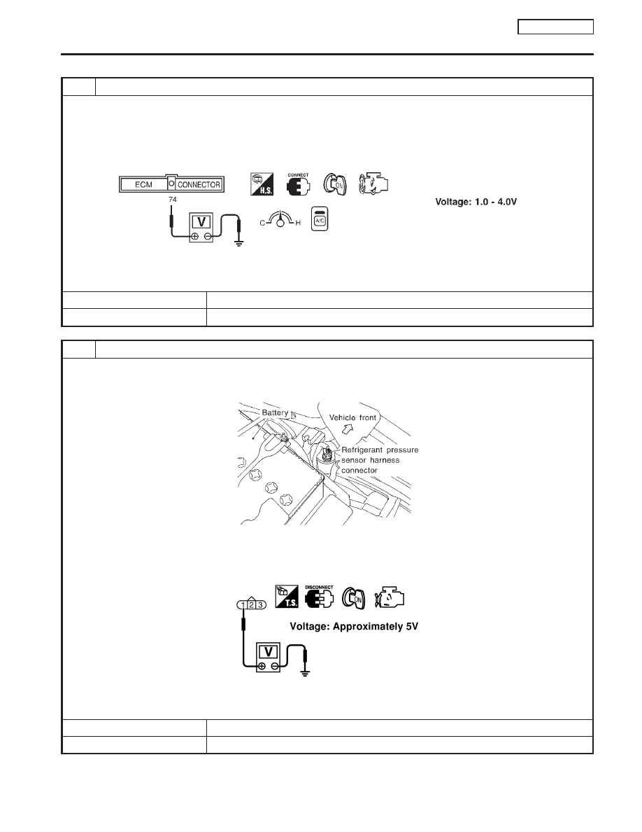
CHECK REFRIGERANT PRESSURE SENSOR OVERALL FUNCTION

1. Start engine and warm it up to normal operating temperature.
2. Turn A/C switch and blower switch “ON”.
3. Check voltage between ECM terminal 74 and ground with CONSULT-II or tester.

SEF952XA

OK or NG

OK

©

INSPECTION END

NG

©

GO TO 2.

2

CHECK REFRIGERANT PRESSURE SENSOR POWER SUPPLY CIRCUIT

1. Turn A/C switch and blower switch “OFF”.
2. Stop engine.
3. Disconnect refrigerant pressure sensor harness connector.

JEF147Y

4. Turn ignition switch “ON”.
5. Check voltage between refrigerant pressure sensor terminal 1 and ground with CONSULT-II or tester.

NEF243A

OK or NG

OK

©

GO TO 4.

NG

©

GO TO 3.

REFRIGERANT PRESSURE SENSOR

QG16

I

18DE

Diagnostic Procedure

EC-349

3

DETECT MALFUNCTIONING PART

Check the following.

I

Harness connectors E90, F73

I

Harness for open or short between ECM and refrigerant pressure sensor

©

Repair harness or connectors.

4

CHECK REFRIGERANT PRESSURE SENSOR GROUND CIRCUIT

1. Turn ignition switch “OFF”.
2. Check harness continuity between refrigerant pressure sensor terminal 3 and engine ground. Refer to Wiring Diagram.

Continuity should exist.

3. Also check harness for short to power.

OK or NG

OK

©

GO TO 6.

NG

©

GO TO 5.

5

DETECT MALFUNCTIONING PART

Check the following.

I

Harness connectors E42, F4

I

Harness for open or short between ECM and refrigerant pressure sensor

©

Repair open circuit or short to power in harness or connectors.

6

CHECK REFRIGERANT PRESSURE SENSOR INPUT SIGNAL CIRCUIT

1. Disconnect ECM harness connector.
2. Check harness continuity between ECM terminal 74 and refrigerant pressure sensor terminal 2. Refer to Wiring Dia-

gram.

Continuity should exist.

3. Also check harness for short to ground and short to power.

OK or NG

OK

©

GO TO 8.

NG

©

GO TO 7.

7

DETECT MALFUNCTIONING PART

Check the following.

I

Harness connectors E42, F4

I

Harness for open or short between ECM and refrigerant pressure sensor

©

Repair open circuit or short to ground or short to power in harness or connectors.

8

CHECK REFRIGERANT PRESSURE SENSOR

Refer to HA section, “Refrigerant pressure sensor”.

OK or NG

OK

©

GO TO 9.

NG

©

Replace refrigerant pressure sensor.

9

CHECK INTERMITTENT INCIDENT

Refer to “TROUBLE DIAGNOSIS FOR INTERMITTENT INCIDENT”, EC-QG-102.

©

INSPECTION END

REFRIGERANT PRESSURE SENSOR

QG16

I

18DE

Diagnostic Procedure (Cont’d)

EC-350

CONSULT-II Reference Value in Data Monitor
Mode

NCEC0548

Specification data are reference values.

MONITOR ITEM

CONDITION

SPECIFICATION

LOAD SIGNAL

I

Ignition switch: ON

Rear window defogger is operating
and/or lighting switch is on.

ON

Rear window defogger is not oper-
ating and lighting switch is not on.

OFF

HEATER FAN SW

I

Ignition switch: ON

Blower fan motor is operating

ON

Blower fan motor is not operating

OFF

ECM Terminals and Reference Value

NCEC0549

Specification data are reference values and are measured between each terminal and ground.

CAUTION:

Do not use ECM ground terminals when measuring input/output voltage. Doing so may result in dam-
age to the ECM’s transistor. Use a ground other than ECM terminals, such as the ground.

TER-

MINAL

NO.

WIRE

COLOR

ITEM

CONDITION

DATA (DC Voltage)

50

R

Electric load signal
(Load switch)

[Engine is running]

I

Rear window defogger is operating and/or lighting
switch is on

BATTERY VOLTAGE
(11 - 14V)

[Engine is running]

I

Rear window defogger is not operating and lighting
switch is not on

Approximately 0V

51

LG/B

Blower fan motor switch

[Engine is running]

I

Blower fan motor is operating

Approximately 0V

[Engine is running]

I

Blower fan motor is not operating

Approximately 5V

ELECTRICAL LOAD SIGNAL

QG16

I

18DE

CONSULT-II Reference Value in Data Monitor Mode

EC-351

Wiring Diagram

NCEC0550

YEC255

ELECTRICAL LOAD SIGNAL

QG16

I

18DE

Wiring Diagram

EC-352


Content   ..  196  197  198  199   ..