Nissan Primera P11. Manual - part 197


  Index      Nissan     Nissan Primera P11 (2001 year) - Service and Repair Manual


Search            


Content   ..  195  196  197  198   ..


Nissan Primera P11. Manual - part 197


3

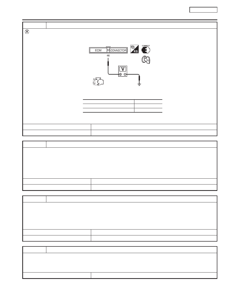
CHECK OVERALL FUNCTION

Without CONSULT-II

1. Start engine.
2. Check voltage between ECM terminal 46 and ground under the following conditions.

SEF148X

MTBL0142

OK or NG

OK

©

INSPECTION END

NG

©

GO TO 4.

4

CHECK GROUND CIRCUIT

1. Turn ignition switch “OFF”.
2. Disconnect power steering oil pressure switch harness connector.
3. Check harness continuity between power steering oil pressure switch harness terminal 2 and engine ground.

Refer to wiring diagram.

Continuity should exist.

4. Also check harness for short to ground and short to power.

OK or NG

OK

©

GO TO 5.

NG

©

Repair open circuit or short to ground or short to power in harness or connectors.

5

CHECK INPUT SIGNAL CIRCUIT

1. Disconnect ECM harness connector.
2. Check harness continuity between ECM terminal 46 and power steering oil pressure switch harness terminal 1.

Refer to wiring diagram.

Continuity should exist.

3. Also check harness for short to ground and short to power.

OK or NG

OK

©

GO TO 7.

NG

©

GO TO 6.

6

DETECT MALFUNCTIONING PART

Check the following.

I

Harness connectors F4, E42

I

Harness for open or short between ECM and power steering oil pressure switch

©

Repair open circuit or short to ground or short to power in harness or connectors.

Condition

Voltage

When steering wheel is turned quickly

Approximately 0V

Except above

Approximately 5V

POWER STEERING OIL PRESSURE SWITCH

QG16

I

18DE

Diagnostic Procedure (Cont’d)

EC-345

7

CHECK POWER STEERING OIL PRESSURE SWITCH

Refer to “Component Inspection”, EC-QG-346.

OK or NG

OK

©

GO TO 8.

NG

©

Replace power steering oil pressure switch.

8

CHECK INTERMITTENT INCIDENT

Perform “TROUBLE DIAGNOSIS FOR INTERMITTENT INCIDENT”, EC-QG-102.

©

INSPECTION END

Component Inspection

NCEC0455

POWER STEERING OIL PRESSURE SWITCH

NCEC0455S01

1.

Disconnect power steering oil pressure switch harness con-
nector then start engine.

2.

Check continuity between terminals 1 and 2.
Refer to wiring diagram.

Conditions

Continuity

Steering wheel is being turned.

Yes

Steering wheel is not being turned.

No

If NG, replace power steering oil pressure switch.

POWER STEERING OIL PRESSURE SWITCH

QG16

I

18DE

Diagnostic Procedure (Cont’d)

EC-346

JEF147Y

Description

NLEC0580

The refrigerant pressure sensor is installed at the liquid tank of the
air conditioner system. The sensor uses an electrostatic volume
pressure transducer to convert refrigerant pressure to voltage. The
voltage signal is sent to ECM, and ECM controls cooling fan sys-
tem.

SEF099X

ECM Terminals and Reference Value

NLEC0581

Specification data are reference values and are measured between each terminal and ground.

CAUTION:

Do not use ECM ground terminals when measuring input/output voltage. Doing so may result in dam-
age to the ECM’s transistor. Use a ground other than ECM terminals, such as the ground.

TERMI-

NAL

NO.

WIRE

COLOR

ITEM

CONDITION

DATA (DC Voltage)

58

B

Sensor’s ground

[Engine is running]

I

Warm-up condition

I

Idle speed

Approximately 0V

74

R/L

Refrigerant pressure
sensor

[Engine is running]

I

Warm-up condition

I

Both A/C switch and blower switch are “ON”
(Compressor operates.)

1.0 - 4.0V

111

G

Sensor’s power supply

[Ignition switch “ON”]

Approximately 5V

REFRIGERANT PRESSURE SENSOR

QG16

I

18DE

Description

EC-347

Wiring Diagram

YEC790

: Detectable line for DTC

: Non-detectable line for DTC

REFRIGERANT
SENSOR

ECM

REFRIGERANT PRESSURE SENSOR

QG16

I

18DE

Wiring Diagram

EC-348


Content   ..  195  196  197  198   ..