Nissan Primera P11. Manual - part 187


  Index      Nissan     Nissan Primera P11 (2001 year) - Service and Repair Manual


Search            


Content   ..  185  186  187  188   ..


Nissan Primera P11. Manual - part 187


Description

NCEC0349

SYSTEM DESCRIPTION

NCEC0349S01

Sensor

Input Signal to ECM

ECM

function

Actuator

Crankshaft position sensor (POS)

Engine speed

EGR control EGR volume control valve

Mass air flow sensor

Amount of intake air

Engine coolant temperature sensor

Engine coolant temperature

Ignition switch

Start signal

Throttle position sensor

Throttle position

Vehicle speed sensor or ABS actuator and
electric unit (control unit)

Vehicle speed

Battery

Battery voltage

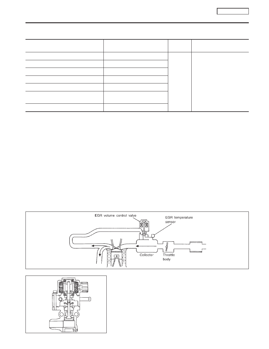
This system controls flow rate of EGR led from exhaust manifold
to intake manifold. The opening of the EGR by-pass passage in the
EGR volume control valve changes to control the flow rate. A
built-in step motor moves the valve in steps corresponding to the
ECM output pulses. The opening of the valve varies for optimum
engine control. The optimum value stored in the ECM is determined
by considering various engine conditions. The EGR volume control
valve remains close under the following conditions.

I

Extremely light load engine operation

I

Mass air flow sensor malfunction

I

Engine idling

I

Low engine coolant temperature

I

Excessively high engine coolant temperature

I

High-speed engine operation

I

Wide open throttle

I

Low battery voltage

I

Engine starting

COMPONENT DESCRIPTION

NCEC0349S02

EGR Volume Control Valve

NCEC0349S0201

The EGR volume control valve uses a step motor to control the flow
rate of EGR from exhaust manifold. This motor has four winding
phases. It operates according to the output pulse signal of the
ECM. Two windings are turned ON and OFF in sequence. Each
time an ON pulse is issued, the valve opens or closes, changing
the flow rate. When no change in the flow rate is needed, the ECM
does not issue the pulse signal. A certain voltage signal is issued
so that the valve remains at that particular opening.

SEF551W

SEF552W

DTC P1402 EGR FUNCTION (OPEN) (IF SO EQUIPPED)

QG16

I

18DE

Description

EC-305

CONSULT-II Reference Value in Data Monitor
Mode

NCEC0539

Specification data are reference values.

MONITOR ITEM

CONDITION

SPECIFICATION

EGR TEMP SEN

I

Engine: After warming up

Less than 4.5V

EGR VOL CON/V

I

Engine: After warming up

I

Air conditioner switch: “OFF”

I

Shift lever: “N”

I

No-load

Idle

0 step

Revving engine up to 3,000 rpm
quickly

10 - 55 step

ECM Terminals and Reference Value

NCEC0540

Specification data are reference values, and are measured between each terminal and ground.

CAUTION:

Do not use ECM ground terminals when measuring input/output voltage. Doing so may result in dam-
age to the ECM’s transistor. Use a ground other than ECM terminals, such as the ground.

TERMI-

NAL

NO.

WIRE

COLOR

ITEM

CONDITION

DATA (DC Voltage)

8
9

17
18

W/B
SB
G/R
R/Y

EGR volume control valve

[Engine is running.]

I

Warm-up condition

I

Rev engine up from 2,000 to 4,000 rpm.

0 - 14V

58

B

Sensor’s ground

[Engine is running.]

I

Warm-up condition

I

Idle speed

0V

72

PU

EGR temperature sensor

[Engine is running.]

I

Warm-up condition

I

Idle speed

Less than 4.5V

[Engine is running.]

I

Warm-up condition

I

EGR system is operating.

0 - 1.0V

On Board Diagnosis Logic

NCEC0350

If EGR temperature sensor detects EGR flow under the condition
that does not call for EGR, a high-flow malfunction is diagnosed.

DTC No.

Malfunction is detected when ...

Check Items (Possible Cause)

P1402
1402

I

EGR flow is detected under conditions that do not call for
EGR.

I

Harness or connectors
(The valve circuit is open or shorted.)

I

EGR volume control valve leaking or stuck open

I

EGR temperature sensor

SEF073P

DTC P1402 EGR FUNCTION (OPEN) (IF SO EQUIPPED)

QG16

I

18DE

CONSULT-II Reference Value in Data Monitor Mode

EC-306

DTC Confirmation Procedure

NCEC0351

NOTE:
If “DTC Confirmation Procedure” has been previously conducted,
always turn ignition switch “OFF” and wait at least 9 seconds
before conducting the next test.
TESTING CONDITION:

I

Always perform at a temperature above −10°C (14°F).

I

Engine coolant temperature and EGR temperature must
be verified in “DATA MONITOR” mode with CONSULT-II
before starting DTC WORK SUPPORT test. If it is out of
range below, the test cannot be conducted.
COOLAN TEMP/S: −10 to 40°C (14 to 104°F)*
EGR TEMP SEN: Less than 4.8V
If the values are out of the ranges indicated above, park
the vehicle in a cool place and allow the engine tempera-
ture to stabilize. Do not attempt to reduce the engine cool-
ant or EGR temperature with a fan or means other than
ambient air. Doing so may produce an inaccurate diagnos-
tic result.

*: Although CONSULT-II screen displays “−10 to 40°C (14 to

104°F)” as a range of engine coolant temperature, ignore it.

PEF347U

SEF127X

DTC P1402 EGR FUNCTION (OPEN) (IF SO EQUIPPED)

QG16

I

18DE

DTC Confirmation Procedure

EC-307

With CONSULT-II

1)

Turn ignition switch “OFF” and wait at least 9 seconds, then
turn ignition switch “ON”.

2)

Select “EGR SYSTEM P1402” of “EGR SYSTEM” in “DTC
WORK SUPPORT” mode with CONSULT-II.

3)

Touch “START”. Follow instructions of CONSULT-II.

4)

Start engine and let it idle until “TESTING” on CONSULT-II
screen is turned to “COMPLETED”. (It will take 45 seconds or
more.)
If “TESTING” is not displayed after 5 minutes, turn ignition
“OFF” and cool the engine coolant temperature to the
range of −10 to 40°C (14 to 104°F). Retry from step 1.

5)

Make sure that “OK” is displayed after touching “SELF-DIAG
RESULTS”.

If

“NG”

is

displayed,

refer

to

“Diagnostic

Procedure”, EC-QG-310.

With GST

1)

Turn ignition switch “ON” and select “MODE 1” with GST.

2)

Check that engine coolant temperature is within the range of
−10 to 40°C (14 to 104°F).

3)

Check that voltage between ECM terminal 72 (EGR tempera-
ture sensor signal) and ground is less than 4.8V.

4)

Start engine and let it idle for at least 45 seconds.

5)

Stop engine.

6)

Perform from step 1 to 4.

7)

Select “MODE 3” with GST.

8)

If DTC is detected, go to “Diagnostic Procedure”, EC-QG-310.

NEF115A

NEF116A

PEF897U

DTC P1402 EGR FUNCTION (OPEN) (IF SO EQUIPPED)

QG16

I

18DE

DTC Confirmation Procedure (Cont’d)

EC-308


Content   ..  185  186  187  188   ..