Nissan Primera P11. Manual - part 143
Diagnostic Procedure
NCEC0085
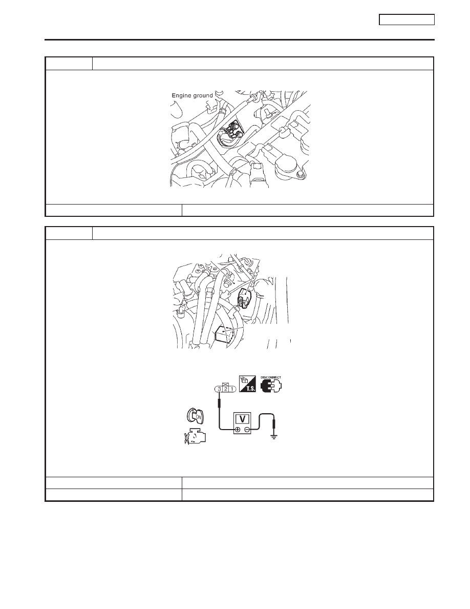
1
RETIGHTEN GROUND SCREWS
1. Turn ignition switch “OFF”.
2. Loosen and retighten engine ground screws.
SEF994W
©
GO TO 2.
2
CHECK POWER SUPPLY
1. Disconnect throttle position sensor harness connector.
NEF246A
2. Turn ignition switch “ON”.
3. Check voltage between terminal 3 and ground with CONSULT-II or tester.
SEF209W
Voltage: Approximately 5V
OK or NG
OK
©
GO TO 3.
NG
©
Repair harness or connectors.
Throttle body
Throttle position sensor
harness connector
IACV-AAC valve
harness connector
DTC P0120 THROTTLE POSITION SENSOR
QG16
I
18DE
Diagnostic Procedure
EC-129