Nissan Primera P11. Manual - part 142


  Index      Nissan     Nissan Primera P11 (2001 year) - Service and Repair Manual


Search            


Content   ..  140  141  142  143   ..


Nissan Primera P11. Manual - part 142


Component Description

NCEC0079

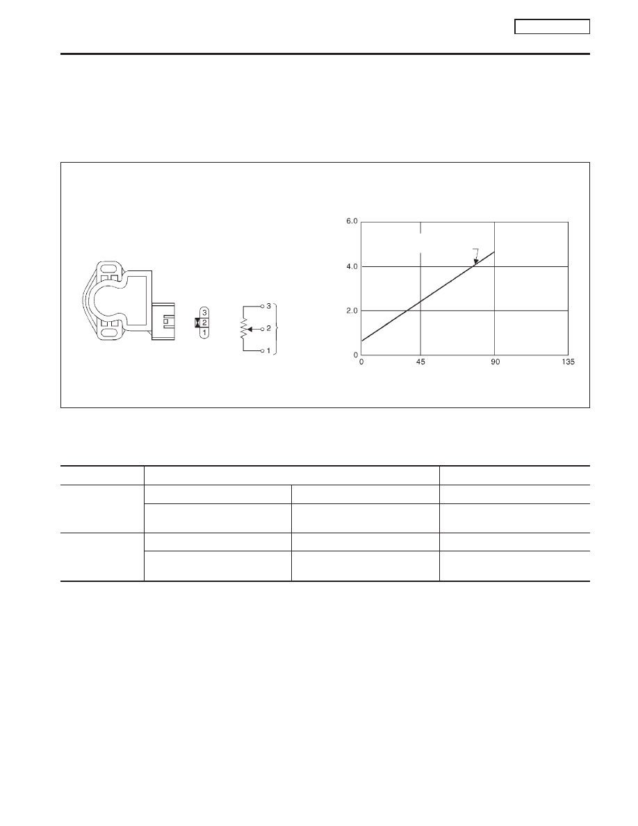
The throttle position sensor responds to the accelerator pedal movement. This sensor is a kind of potentiom-
eter which transforms the throttle position into output voltage, and emits the voltage signal to the ECM. In
addition, the sensor detects the opening and closing speed of the throttle valve and feeds the voltage signal
to the ECM.
Idle position of the throttle valve is determined by the ECM receiving the signal from the throttle position sen-
sor. This sensor controls engine operation such as fuel cut. On the other hand, the “Wide open and closed
throttle position switch”, which is built into the throttle position sensor unit, is not used for engine control.

CONSULT-II Reference Value in Data Monitor
Mode

NCEC0080

Specification data are reference values.

MONITOR ITEM

CONDITION

SPECIFICATION

THRTL POS SEN

I

Engine: Idle

Throttle valve fully closed

0.35 - 0.65V

I

Ignition switch: ON
(Engine stopped)

Throttle valve fully opened

3.7 - 4.5V

ABSOL TH

P/S

I

Engine: Idle

Throttle valve fully closed

0.0°

I

Ignition switch: ON
(Engine stopped)

Throttle valve fully opened

Approx. 80°

NEF245A

Throttle
position
sensor

Output

voltage

between

terminal

No.

2

and

3

(V)

Throttle valve opening angle (deg)

Output voltage between
terminal No. 2 and 3)

Supply voltage: 5V
(Applied between terminal
No. 1 and 3)

DTC P0120 THROTTLE POSITION SENSOR

QG16

I

18DE

Component Description

EC-125

ECM Terminals and Reference Value

=NCEC0081

Specification data are reference values and are measured between each terminal and ground.

CAUTION:

Do not use ECM ground terminals when measuring input/output voltage. Doing so may result in dam-
age to the ECM’s transistor. Use a ground other than ECM terminals, such as the ground.

TERMI-

NAL

NO.

WIRE

COLOR

ITEM

CONDITION

DATA (DC Voltage)

58

B

Sensors’ ground

[Engine is running]

I

Warm up condition

I

Idle speed

Approximately 0V

92

Y

Throttle position sensor

[Engine is running]

I

Accelerator pedal fully released

0.35 - 0.65V

[Ignition switch “ON”]

I

Accelerator pedal fully depressed

3.7 - 4.5V

111

G

Sensors’ power supply

[Ignition switch “ON”]

Approximately 5V

On Board Diagnosis Logic

NCEC0082

DTC No.

Malfunction is detected when ...

Check Items (Possible Cause)

P0120*
0120

An excessively low or high voltage from the sensor is
sent to ECM while driving.

I

Harness or connectors
(The throttle position sensor circuit is open or
shorted.)

I

Throttle position sensor

*: When this malfunction is detected, the ECM enters fail-safe mode and the MI lights up.

Detected items

Engine operating condition in fail-safe mode

Throttle position sensor
circuit

Throttle position will be determined based on the injected fuel amount and the engine speed.
Therefore, acceleration will be poor.

Condition

Driving condition

When engine is idling

Normal

When accelerating

Poor acceleration

DTC Confirmation Procedure

NCEC0083

NOTE:
If “DTC Confirmation Procedure” has been previously conducted,
always turn ignition switch “OFF” and wait at least 9 seconds
before conducting the next test.

CAUTION:

Always drive vehicle at a safe speed.
TESTING CONDITION:

I

Before performing the following procedure, confirm that
battery voltage is more than 10V at idle.

I

This test may be conducted with the drive wheels lifted in
the shop or by driving the vehicle. If a road test is
expected to be easier, it is unnecessary to lift the vehicle.

DTC P0120 THROTTLE POSITION SENSOR

QG16

I

18DE

ECM Terminals and Reference Value

EC-126

With CONSULT-II

1)

Turn ignition switch “ON” and select “DATA MONITOR” mode
with CONSULT-II.

2)

Start engine and maintain the following conditions for at least
5 consecutive seconds.

VHCL SPEED SE

More than 4 km/h (2 MPH)

Selector lever

Suitable position except “N” position

3)

If 1st trip DTC is detected, go to “Diagnostic Procedure”, EC-
QG-129.

With GST

Follow the procedure “With CONSULT-II” above.

PEF651U

DTC P0120 THROTTLE POSITION SENSOR

QG16

I

18DE

DTC Confirmation Procedure (Cont’d)

EC-127

Wiring Diagram

NCEC0084

YEC064A

DTC P0120 THROTTLE POSITION SENSOR

QG16

I

18DE

Wiring Diagram

EC-128


Content   ..  140  141  142  143   ..