Nissan Primera P11. Manual - part 133


  Index      Nissan     Nissan Primera P11 (2001 year) - Service and Repair Manual


Search            


Content   ..  131  132  133  134   ..


Nissan Primera P11. Manual - part 133


NEF066A

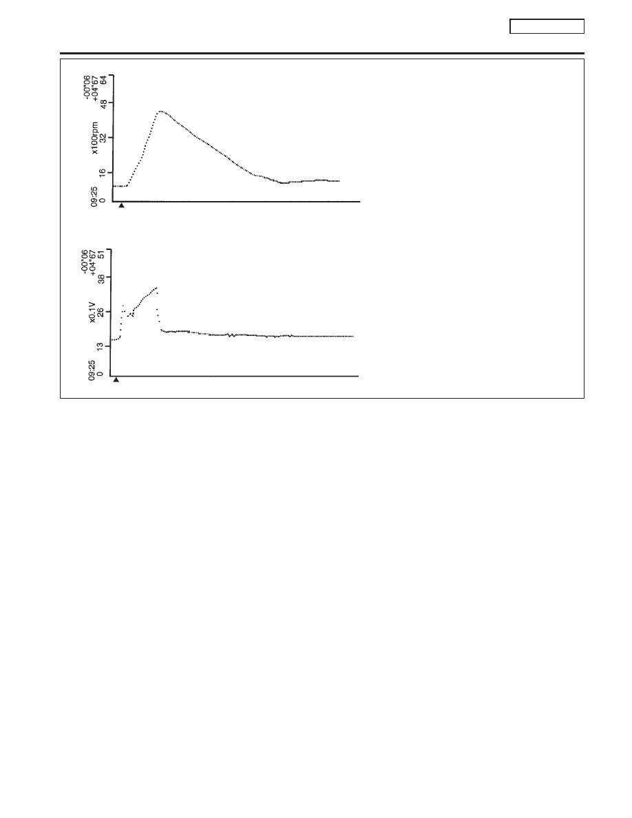
“ENG SPEED” should increase gradually while
depressing the accelerator pedal and should
decrease gradually after releasing
the pedal without any intermittent drop.

“MAS A/F SE-B1” should increase when
depressing the accelerator pedal and should
decrease at the moment “THRTL POS SEN” is
closed (accelerator pedal is released).

MAS

A/F

SE-B1

ENG

SPEED

TROUBLE DIAGNOSIS — GENERAL DESCRIPTION

QG16

I

18DE

Major Sensor Reference Graph in Data Monitor Mode (Cont’d)

EC-89

SEF601Y

SEF170YA

TROUBLE DIAGNOSIS — GENERAL DESCRIPTION

QG16

I

18DE

Major Sensor Reference Graph in Data Monitor Mode (Cont’d)

EC-90

ECM Terminals and Reference Value

NCEC0044

PREPARATION

NCEC0044S01

1.

ECM is located behind the center console. For this inspection:
Remove the front passenger center console panel.

2.

Remove ECM harness protector.

3.

Perform all voltage measurements with the connector con-
nected. Extend tester probe as shown to perform tests easily.

I

Open harness securing clip to make testing easier.

I

Use extreme care not to touch 2 pins at one time.

I

Data is for comparison and may not be exact.

ECM HARNESS CONNECTOR TERMINAL LAYOUT

NCEC0044S02

ECM INSPECTION TABLE

NCEC0044S03

Specification data are reference values and are measured between
each terminal and ground.

CAUTION:

Do not use ECM ground terminals when measuring input/
output voltage. Doing so may result in damage to the ECM’s
transistor. Use a ground other than ECM terminals, such as
the ground.

SEF967W

SEF367I

SEF970W

TROUBLE DIAGNOSIS — GENERAL DESCRIPTION

QG16

I

18DE

ECM Terminals and Reference Value

EC-91

TER-

MINAL

NO.

WIRE

COLOR

ITEM

CONDITION

DATA (DC Voltage)

1

Y/R

Intake valve timing con-
trol solenoid valve

[Engine is running]

I

Idle speed

BATTERY VOLTAGE
(11 - 14V)

[Engine is running]

I

Lift up drive wheels and shift gear “ON”

I

Rev engine up from 1,200 to 3,000 rpm

Approximately 0V

3

W/R

Heated oxygen sensor
2 heater (rear)

[Engine is running]

I

Engine speed is below 3,600 rpm

I

After driving for 2 minutes at a speed of 70
km/h (43 MPH) or more

Approximately 0.7V

[Ignition switch “ON”]

I

Engine stopped

I

Engine speed is above 3,600 rpm

BATTERY VOLTAGE
(11 - 14V)

4

L

Heated oxygen sensor
1 heater (front)

[Engine is running]

I

Engine speed is below 3,200 rpm

Approximately 0V

[Engine is running]

I

Engine speed is above 3,200 rpm

BATTERY VOLTAGE
(11 - 14V)

6
7

15
16

BR
Y/B
P
OR

IACV-AAC valve

[Engine is running]

I

Warm-up condition

I

Idle speed

0.1 - 14V

8*
9*

17*
18*

W/B
SB
G/R
R/Y

EGR volume control
valve

[Engine is running]

I

Warm-up condition

I

Rev engine up from 2,000 to 4,000 rpm

0 - 14V

13

LG/R

Cooling fan relay

[Engine is running]

I

Cooling fan is not operating

BATTERY VOLTAGE
(11 - 14V)

[Engine is running]

I

Cooling fan is operating

Approximately 0V

14

P/B

EVAP canister purge
volume control valve
(ON/OFF duty)

[Engine is running]

I

Warm-up condition

I

Accelerator pedal depressed

5 - 12V

SEF975W

21

B/P

Fuel pump relay

[Ignition switch “ON”]

I

For 1 second after turning ignition switch “ON”

[Engine is running]

0 - 1V

[Ignition switch “ON”]

I

More than 1 second after turning ignition switch
“ON”

BATTERY VOLTAGE
(11 - 14V)

22

OR/L

Malfunction indicator

[Ignition switch “ON”]

0 - 1V

[Engine is running]

I

Idle speed

BATTERY VOLTAGE
(11 - 14V)

23

L/W

Air conditioner relay

[Engine is running]

I

Both A/C switch and blower switch are “ON”

Approximately 0V

[Engine is running]

I

A/C switch is “OFF”

BATTERY VOLTAGE
(11 - 14V)

*: If so equipped

TROUBLE DIAGNOSIS — GENERAL DESCRIPTION

QG16

I

18DE

ECM Terminals and Reference Value (Cont’d)

EC-92


Content   ..  131  132  133  134   ..