Nissan Primera P11. Manual - part 104
DIAGNOSTIC PROCEDURE
INSPECTION START
(Glow relay signal circuit)
CHECK MAIN POWER SUPPLY.
Check power supply to ECCS-D relay.
Refer to “TROUBLE DIAGNOSIS FOR
POWER SUPPLY” (EC-CD-59).
CHECK POWER SUPPLY.
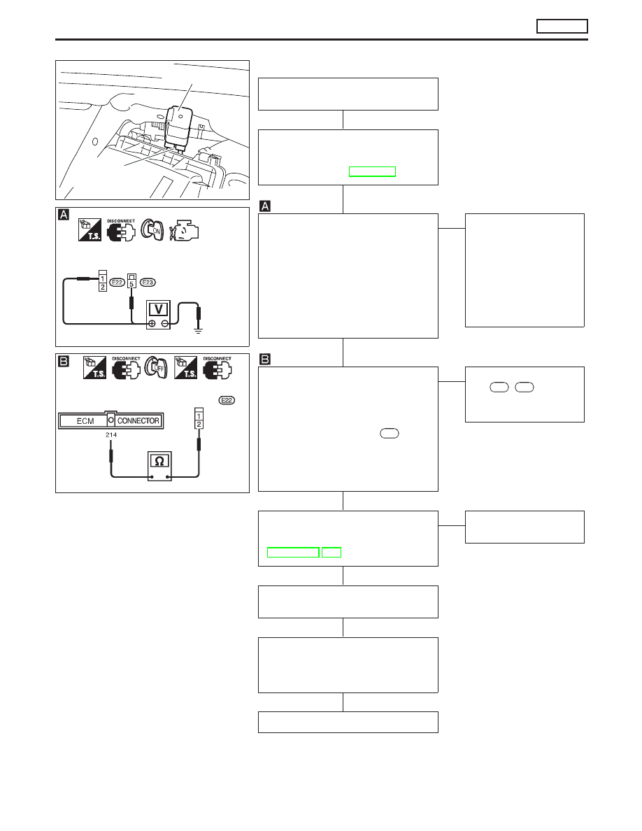
1. Turn ignition switch to the “LOCK”
position.
2. Disconnect glow relay.
3. Turn ignition switch to the “ON” posi-
tion.
4. Check voltage between glow relay
connector terminals
p
1
,
p
5
and
ground with tester.
Voltage: Battery voltage
OK
E
NG
Check the following:
●
15A fuse
●
80A fusible link
●
Harness continuity
between glow relay
and fuse.
If NG, replace fuse or
fusible link or repair har-
ness or connectors.
CHECK OUTPUT SIGNAL CIRCUIT.
1. Turn ignition switch to the “LOCK”
position.
2. Disconnect ECM harness connector.
3. Check harness continuity between
ECM connector terminal
214
and
glow relay connector terminal
p
2
.
Continuity should exist.
If OK, check harness for short-cir-
cuit.
OK
E
NG
Check harness connec-
tors
F96
,
E89
Repair harness or con-
nectors.
CHECK GLOW PLUG AND GLOW
RELAY.
Refer to “COMPONENT INSPECTION”
(EC-CD-124, 125).
OK
E
NG
Replace glow plug or
glow relay.
Disconnect and reconnect harness
connectors in the circuit. Then retest.
Trouble is not fixed
Check ECM pin terminals for damage
and check the connection of ECM har-
ness connector. Reconnect ECM har-
ness connector and retest.
INSPECTION END
NEF835
Glow relay
Glow relay
harness connector
YEC370
Glow relay con-
nector
NEF215A
Glow relay
connector
H
H
H
H
H
H
H
TROUBLE DIAGNOSES 14
CD20T
Glow Control System (Cont’d)
EC-121