Nissan Primera P11. Manual - part 52


  Index      Nissan     Nissan Primera P11 (2001 year) - Service and Repair Manual


Search            


Content   ..  50  51  52  53   ..


Nissan Primera P11. Manual - part 52


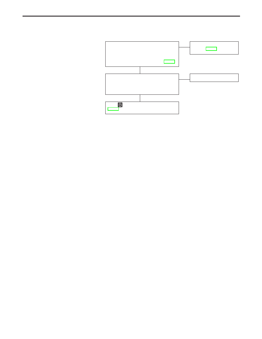
Diagnostic Procedure 6 (ABS works
frequently)

CHECK WHEEL SENSOR.
1. Check wheel sensor connector for termi-

nal damage or loose connections.

2. Perform wheel sensor mechanical check.

Refer to Diagnostic Procedure 1, BR-77.

OK

E

NG

Perform Preliminary check.
Refer to BR-59.

CHECK FRONT AXLES
Check front axles for excessive looseness.
Refer to FA and RA section (“Front/Rear
Wheel Bearing”, “ON-VEHICLE SERVICE”).

OK

E

NG

Repair.

Go to

in Diagnostic Procedure 8,

BR-86.

H

H

TROUBLE DIAGNOSES FOR SYMPTOMS

BR-85

Diagnostic Procedure 7 (Unexpected pedal
action)

CHECK BRAKE PEDAL STROKE.
Check brake pedal stroke. Is stroke
excessively large?

No

E

Yes

Perform Preliminary
Check, refer to BR-59.

CHECK BRAKE PERFORMANCE
Disconnect ABS actuator and electric
unit connector and check whether brake
is effective.

Yes

E

No

Perform Preliminary
Check, refer to BR-59.

CHECK WARNING LAMP ACTIVATE.
Ensure warning lamp remains off while
driving.

OK

E

NG

Carry out self-diagnosis.
Refer to BR-67.

CHECK WHEEL SENSOR.
1. Check wheel sensor connector for

terminal damage or loose connec-
tion.

2. Perform wheel sensor mechanical

check.
Refer to Diagnostic Procedure 1,
BR-77.

OK

E

NG

Repair.

CHECK HARNESS CONNECTOR.
Check ABS actuator and electric unit
pin terminals fir damage or the connec-
tion of ABS actuator and electric unit
harness connector.
Reconnect ABS actuator and electric
unit harness connector. Then retest.

Diagnostic Procedure 8 (Long stopping
distance)

CHECK ABS PERFORMANCE
Disconnect ABS actuator and electric
unit connector and check whether stop-
ping distance is still long.

Yes

E

No

Go to

in Diagnostic

Procedure 7, BR-86.

Perform Preliminary Check and air
bleeding.

Note: Stopping distance may be larger than vehicles without

ABS when road condition is slippery.

SBR540A

NBR284

ABS warning light

H

H

H

H

H

TROUBLE DIAGNOSES FOR SYMPTOMS

BR-86

Diagnostic Procedure 9 (ABS does not
work.)

CHECK WARNING LAMP ACTIVATE.
Does the ABS warning lamp activate?

No

E

Yes

Carry out self-diagnosis.
Refer to BR-67.

Go to

in Diagnostic Procedure 7,

BR-86.

Note: ABS does not work when vehicle speed is under 10

km/h (6 MPH).

Diagnostic Procedure 10 (Pedal vibration and
noise)

INSPECTION START
1. Apply brake.
2. Start engine.
3. Does the symptom appear only

when engine is started?

No

E

Yes

Carry out self-diagnosis.
Refer to BR-67.

CHECK IF SYMPTOM APPEARS.
Does the symptom appear when elec-
trical equipment switches (such as
headlamp) are operated?

Yes

E

No

Go to

in Diagnostic

Procedure 7, BR-86.

CHECK WHEEL SENSOR.
Check wheel sensor shield ground. For
location of shield ground, refer to wiring
diagram and “HARNESS LAYOUT” in
EL section.

OK

E

NG

Repair wheel sensor.

CHECK HARNESS CONNECTOR.
Check ABS actuator and electric unit
pin terminals for damage or the con-
nection of ABS actuator and electric
unit harness connector.
Reconnect ABS actuator and electric
unit harness connector. Then retest.

Note: ABS may operate and cause vibration under any of

the following conditions.

SAT797A

Brake pedal

H

H

H

H

TROUBLE DIAGNOSES FOR SYMPTOMS

BR-87

Applying brake gradually when shifting or operating clutch.

Low friction (slippery) road.

High speed concerning.

Driving over bumps and pot holes.

Engine speed is over 5,000 rpm with vehicle stopped.

Diagnostic Procedure 11 (ABS Warning lamp
does not come on when ignition switch is
turned ON)

CHECK FUSE.
Check 10A fuse

12

. For fuse layout,

refer to POWER SUPPLY ROUTING in
EL section.

OK

E

NG

Replace fuse.

CHECK ABS CONTROL UNIT
POWER SUPPLY CIRCUIT.
1. Install 10A fuse.
2. Disconnect ABS actuator and elec-

tric unit connector.

3. Check voltage between control unit

connector terminal 21, 22 and
ground after turning ignition switch
“ON”.

Yes

E

No

p

A

(Go to next page.)

p

B

(Go to next page.)

NBR415

.

Fuse

Combination meter

ABS
warning
lamp

CVT models
M/T models

ABS control unit

ABS actuator and electric unit

NBR416

ABS ACTUATOR AND

ELECTRIC UNIT CONNECTOR

CVT models
M/T models

H

H

TROUBLE DIAGNOSES FOR SYMPTOMS

Diagnostic Procedure 10 (Pedal vibration
and noise) (Cont’d)

BR-88


Content   ..  50  51  52  53   ..