Nissan Primera P11. Manual - part 51
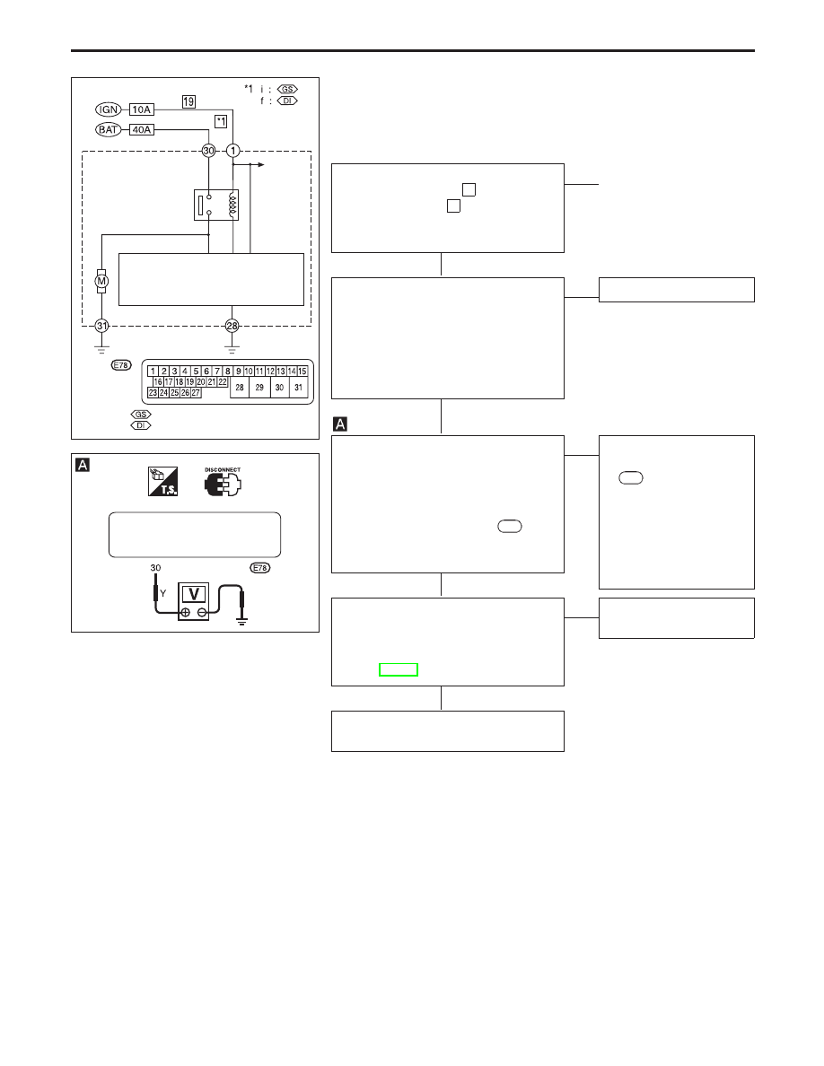
Diagnostic Procedure 3 (Motor Relay or
motor)
(Malfunction code No. 61 for models with
self-diagnosis function)
CHECK FUSIBLE LINK.
Check 40A fusible link
i
(Petrol
engine), fusible link
f
(diesel engine).
For fusible link layout, refer to POWER
SUPPLY ROUTING in EL section.
OK
E
NG
p
A
(Go to next page.)
CHECK CONNECTOR
1. Disconnect ABS actuator and electric
unit connector. Check terminals for
damage or loose connection. Then
reconnect connector.
2. Carry out self-diagnosis again.
Does warning lamp activate again?
Yes
E
No
Inspection end
CHECK MOTOR RELAY POWER SUP-
PLY CIRCUIT.
1. Disconnect ABS actuator and electric
unit connector.
2. Check voltage between ABS actuator
and electric unit connector
E78
(body
side) terminal
p
30
and ground.
Battery voltage should exist.
OK
E
NG
Check the following.
●
Harness connector
E78
●
Harness for open or
short between ABS
actuator and electric
unit and fusible link.
If NG, repair harness or
connector.
CHECK ABS ACTUATOR AND ELEC-
TRIC UNIT GROUND.
Refer to ABS ACTUATOR AND ELEC-
TRIC UNIT GROUND in Ground Circuit
Check, BR-75.
OK
E
NG
Repair harness and termi-
nals.
REPLACE.
Replace ABS actuator and electric unit.
YBR177
Fusible link
Fuse
ABS actuator
and electric
unit
Motor
relay
To
solenoid
valve
relay
ABS control unit
ABS
actuator and
electric unit
connector
: With petrol engine
: With diesel engine
YBR178
ABS ACTUATOR AND
ELECTRIC UNIT CONNECTOR
H
H
H
H
TROUBLE DIAGNOSES FOR SELF-DIAGNOSTIC ITEMS
BR-81