Nissan Primera P11. Manual - part 21
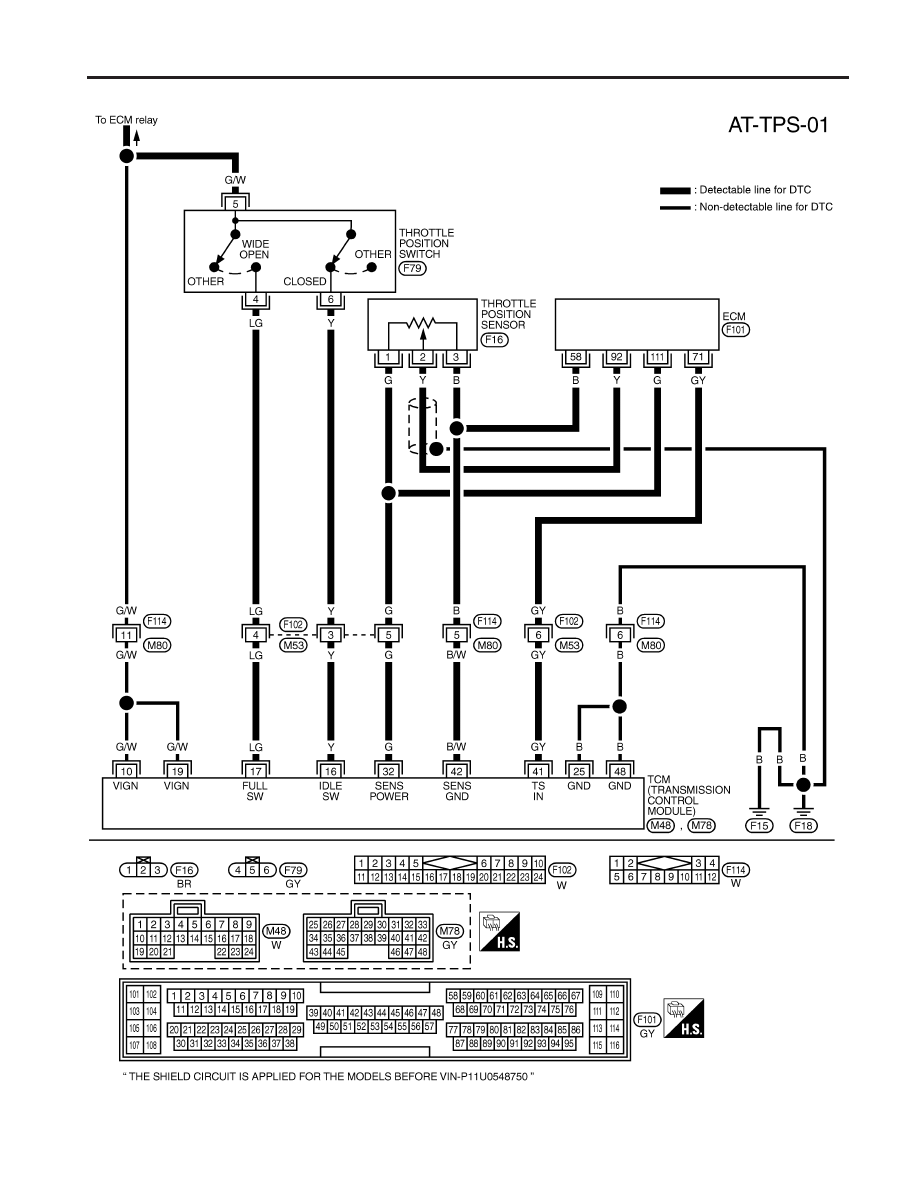
Wiring Diagram — AT — TPS
NCAT0212
YAT252
DTC P1705 THROTTLE POSITION SENSOR
Wiring Diagram — AT — TPS
AT-81
|
|
|
Wiring Diagram — AT — TPS NCAT0212 YAT252 DTC P1705 THROTTLE POSITION SENSOR Wiring Diagram — AT — TPS AT-81 |