Nissan Primera P11. Manual - part 22


  Index      Nissan     Nissan Primera P11 (2001 year) - Service and Repair Manual


Search            


Content   ..  20  21  22  23   ..


Nissan Primera P11. Manual - part 22


Component Inspection

=NCAT0072

THROTTLE POSITION SWITCH

NCAT0072S01

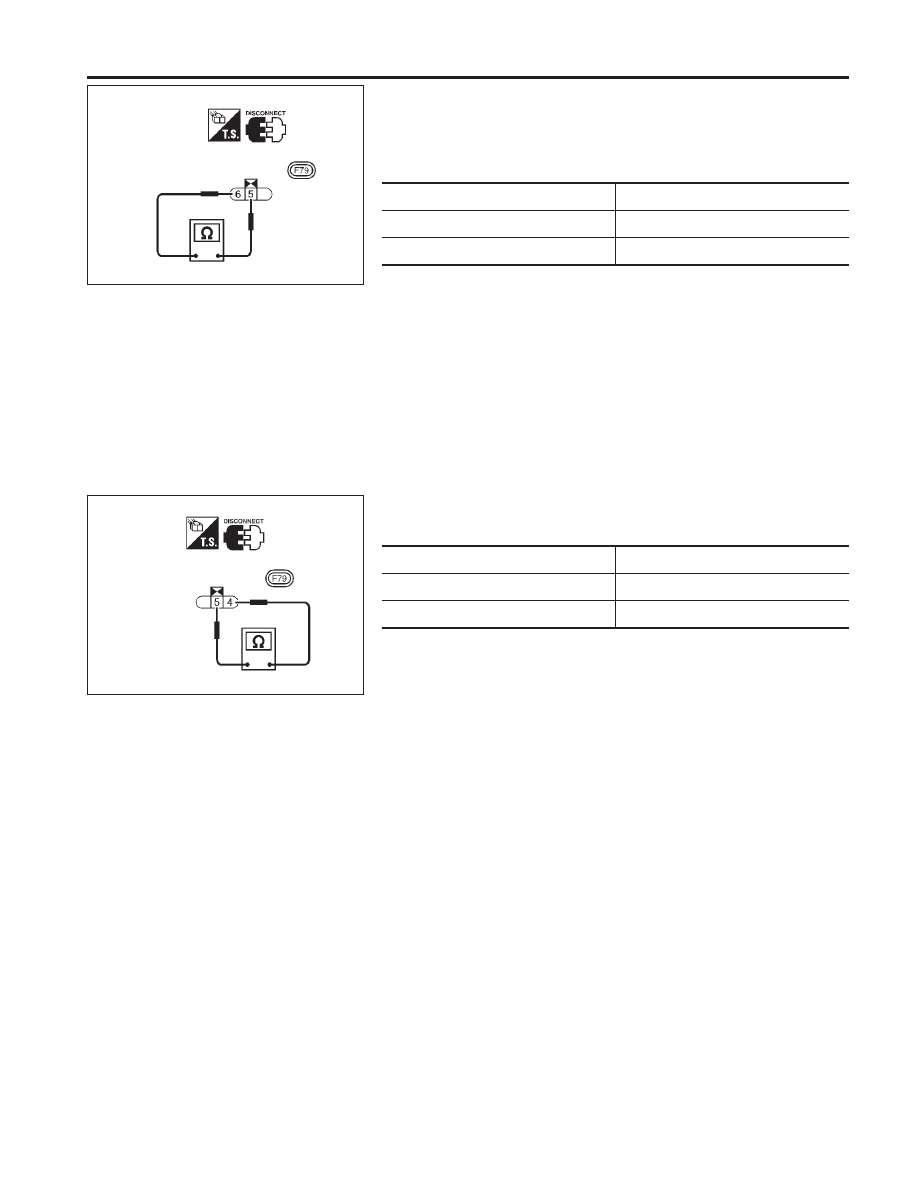
Closed Throttle Position Switch (Idle position)

NCAT0072S0101

I

Check continuity between terminals 5 and 6.

Accelerator pedal condition

Continuity

Released

Yes

Depressed

No

I

To adjust closed throttle position switch, refer to EC section
(“Basic Inspection”, “TROUBLE DIAGNOSIS — Basic Inspec-
tion”).

Wide Open Throttle Position Switch

NCAT0072S0102

I

Check continuity between terminals 5 and 4.

Accelerator pedal condition

Continuity

Released

No

Depressed

Yes

SAT688J

Throttle position switch
harness connector

SAT689J

Throttle position switch
harness connector

DTC P1705 THROTTLE POSITION SENSOR

Component Inspection

AT-85

Description

NCAT0224

I

The step motor is ON/OFF of 4 aspects changes according to
the signal from TCM.
As a result, the flow of line pressure to primary pulley is
changed and pulley ratio is controlled.

CONSULT-II REFERENCE VALUE IN DATA MONITOR
MODE

NCAT0224S01

Remarks: Specification data are reference values.

Monitor item

Condition

Specification

Step motor

The vehicle runs a safe condition and

press/depress accelerator pedal.

ON/OFF

TCM TERMINALS AND REFERENCE VALUE

NCAT0224S02

Remarks: Specification data are reference values.

Terminal

No.

Wire color

Item

Condition

Judgement

standard

11

PU

Step motor

Within 2 seconds after key switch “ON”, the time measurement by
using the pulse width measurement function (Hi level) of CON-
SULT-II.

I

CONSULT-II cable connect to data link connector.

I

This inspection cannot be measured by circuit tester.

30.0 msec

12

L/W

10.0 msec

20

L/Y

30.0 msec

21

P/L

10.0 msec

ON BOARD DIAGNOSIS LOGIC

NCAT0224S03

Diagnostic trouble code

Malfunction is detected when ...

Check items (Possible cause)

: STEP MOTOR/CIRC

When in operating step motor ON and
OFF, there is no proper change in the
voltage of the terminal TCM which corre-
sponds to it.

I

Harness or connectors
(The step motor circuit is open or
shorted.)

I

Step motor

: P1777

: MI Code No. 1777

DTC P1777 STEP MOTOR — CIRCUIT

Description

AT-86

DIAGNOSTIC TROUBLE CODE (DTC) CONFIRMATION
PROCEDURE

NCAT0224S04

CAUTION:

I

Always drive vehicle at a safe speed.

I

Be careful not to rev engine into the red zone on the
tachometer.

NOTE:
If “DIAGNOSTIC TROUBLE CODE CONFIRMATION PROCE-
DURE” has been previously conducted, always turn ignition
switch “OFF” and wait at least 5 seconds before conducting
the next test.

After the repair, perform the following procedure to confirm the
malfunction is eliminated.

With CONSULT-II

1)

Turn ignition switch “ON” and select “DATA MONITOR” mode
for “ENGINE” with CONSULT-II.

2)

Drive vehicle for at least 5 consecutive seconds.
If the check result is “NG”, go to “Diagnostic Procedure”,
AT-89.

With GST

Follow the procedure “With CONSULT-II”.

SAT651J

SAT654J

DTC P1777 STEP MOTOR — CIRCUIT

Description (Cont’d)

AT-87

Wiring Diagram — AT — STM

NCAT0225

YAT208

TCM
(TRANSMISSION
CONTROL MODULE)

: Detectable line for DTC

: Non-detectable line for DTC

CONTROL
VALVE
(STEP MOTOR)

DTC P1777 STEP MOTOR — CIRCUIT

Wiring Diagram — AT — STM

AT-88


Content   ..  20  21  22  23   ..