Nissan Primera P11. Manual - part 12
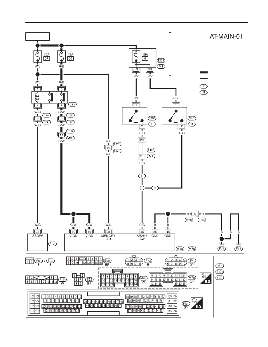
Wiring Diagram — CVT — MAIN
NCAT0031
YAT201
BATTERY
ENGINE
CONTROL
MODULE
RELAY
OFF
ON
STOP
LAMP
SWITCH
FUSE
BLOCK
(J/B)
OFF
ON
STOP
LAMP
SWITCH
: Detectable line for DTC
: Non-detectable line for DTC
: LHD models
: RHD models
Refer to EL-POWER.
FUSE
BLOCK
(J/B)
TCM
(TRANSMISSION
CONTROL
MODULE)
Refer to last page
(foldout page).
ECM
TROUBLE DIAGNOSIS FOR POWER SUPPLY
Wiring Diagram — CVT — MAIN
AT-45