Nissan Primera P11. Manual - part 11
TCM Terminals and Reference Value
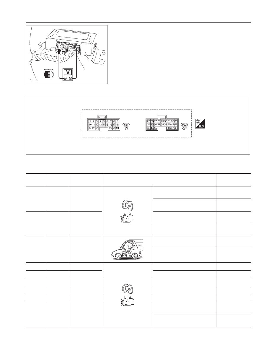
NCAT0030
PREPARATION
NCAT0030S01
I
Measure voltage between each terminal and terminal 25 or 48
by following “TCM INSPECTION TABLE”.
TCM HARNESS CONNECTOR TERMINAL LAYOUT
NCAT0030S02
TCM INSPECTION TABLE
NCAT0030S03
(Data are reference values.)
Terminal
No.
Wire color
Item
Condition
Judgement
standard
1
OR/L
Line pressure
solenoid valve
When releasing accelerator pedal
after warming up engine.
Approx. 2.8V
When depressing accelerator pedal
fully after warming up engine.
Approx. 1.4V
2
P/B
Line pressure
solenoid valve
(with dropping
resistor)
When releasing accelerator pedal
after warming up engine.
Approx. 11.0V
When depressing accelerator pedal
fully after warming up engine.
Approx. 4.0V
3
GY/R
Torque converter
clutch solenoid
valve
When CVT performs lock-up.
Approx. 12.0V
When CVT does not perform lock-
up.
Approx. 0V
5 *1
W/L
DT1
—
—
6 *1
W/PU
DT2
—
—
7 *1
R/W
DT3
—
—
8 *1
L/R
DT5
—
—
9 *1
LG/B
DT4
—
—
10
G/W
Power source
When turning ignition switch to
“ON”.
Battery voltage
When turning ignition switch to
“OFF”.
Approx. 0V
SAT216J
Terminal
p
25
or
p
48
SAT403J
TROUBLE DIAGNOSIS — GENERAL DESCRIPTION
TCM Terminals and Reference Value
AT-41