Nissan Primera P11. Manual - part 13


  Index      Nissan     Nissan Primera P11 (2001 year) - Service and Repair Manual


Search            


Content   ..  11  12  13  14   ..


Nissan Primera P11. Manual - part 13


DIAGNOSTIC TROUBLE CODE (DTC) CONFIRMATION
PROCEDURE

NCAT0032S03

CAUTION:

Always drive vehicle at a safe speed.
NOTE:
If “DIAGNOSTIC TROUBLE CODE CONFIRMATION PROCE-
DURE” has been previously conducted, always turn ignition
switch “OFF” and wait at least 5 seconds before conducting
the next test.
After the repair, perform the following procedure to confirm the
malfunction is eliminated.
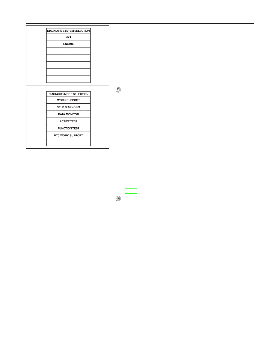
With CONSULT-II

1)

Turn ignition switch “ON” and select “DATA MONITOR” mode
for “CVT” with CONSULT-II.

2)

Make sure that output voltage of CVT fluid temperature sne-
sor is within the range below.

FLUID TEMP SEN: 0.5 - 1.5V

If out of range, drive the vehicle to decrease the voltage
(warm up the fluid) or stop engine to increase the voltage
(cool down the fluid)

3)

Select “DATA MONITOR” mode for “ENGINE” with CONSULT-
II.

4)

Start engine and maintain the following conditions for at least
15 consecutive seconds.

VHCL SPEED SE: 10 km/h (6 MPH) or more
THRTL POS SEN: More than 1.3V
Selector lever: D position
ENG SPEED: 450 rpm or more

If the check result is “NG”, go to “Diagnostic Procedure”,
AT-51.
With GST

Follow the procedure “With CONSULT-II”.

SAT651J

SAT654J

DTC P0705 PARK/NEUTRAL POSITION (PNP) SWITCH

Description (Cont’d)

AT-49

Wiring Diagram — AT — PNP/SW

NCAT0199

YAT251

DTC P0705 PARK/NEUTRAL POSITION (PNP) SWITCH

Wiring Diagram — AT — PNP/SW

AT-50

Diagnostic Procedure

NCAT0033

1

CHECK PNP SWITCH CIRCUIT (With CONSULT-II)

With CONSULT-II

1. Turn ignition switch to “ON” position.

(Do not start engine.)

2. Select “ECU INPUT SIGNALS” in “DATA MONITOR” mode for “CVT” with CONSULT-II.

SAT651J

3. Read out “P/N”, “R”, “D” and “L” position switches moving selector lever to each position.

Check the signal of the selector lever position is indicated properly.

OK or NG

OK

©

GO TO 3.

NG

©

Check the following items:

I

PNP switch
Refer to “Component Inspection”, AT-53.

I

Harness for short or open between ignition switch and PNP switch (Main harness)

I

Harness for short or open between PNP switch and TCM (Main harness)

I

Ignition switch and fuse
Refer to EL section (“POWER SUPPLY ROUTING”).

I

Diode (P, N positions)

2

CHECK PNP SWITCH CIRCUIT (Without CONSULT-II)

Without CONSULT-II

1. Turn ignition switch to “ON” position.

(Do not start engine.)

2. Check voltage between TCM terminals 27, 34, 35, 36 and ground while moving selector lever through each position.

Voltage:

B: Battery voltage
0: 0V

MTBL0312

Terminal No.

Lever position

OK or NG

OK

©

GO TO 3.

NG

©

Check the following items:

I

PNP switch
Refer to “Component Inspection”, AT-53.

I

Harness for short or open between ignition switch and PNP switch (Main harness)

I

Harness for short or open between PNP switch and TCM (Main harness)

I

Ignition switch and fuse
Refer to EL section (“POWER SUPPLY ROUTING”).

I

Diode (P, N positions)

DTC P0705 PARK/NEUTRAL POSITION (PNP) SWITCH

Diagnostic Procedure

AT-51

3

CHECK DTC

Perform Diagnostic Trouble Code (DTC) confirmation procedure, AT-49.

OK or NG

OK

©

INSPECTION END

NG

©

1. Perform TCM input/output signal inspection.
2. If NG, recheck TCM pin terminals for damage or loose connection with harness con-

nector.

DTC P0705 PARK/NEUTRAL POSITION (PNP) SWITCH

Diagnostic Procedure (Cont’d)

AT-52


Content   ..  11  12  13  14   ..