Nissan Frontier D22. Manual - part 505
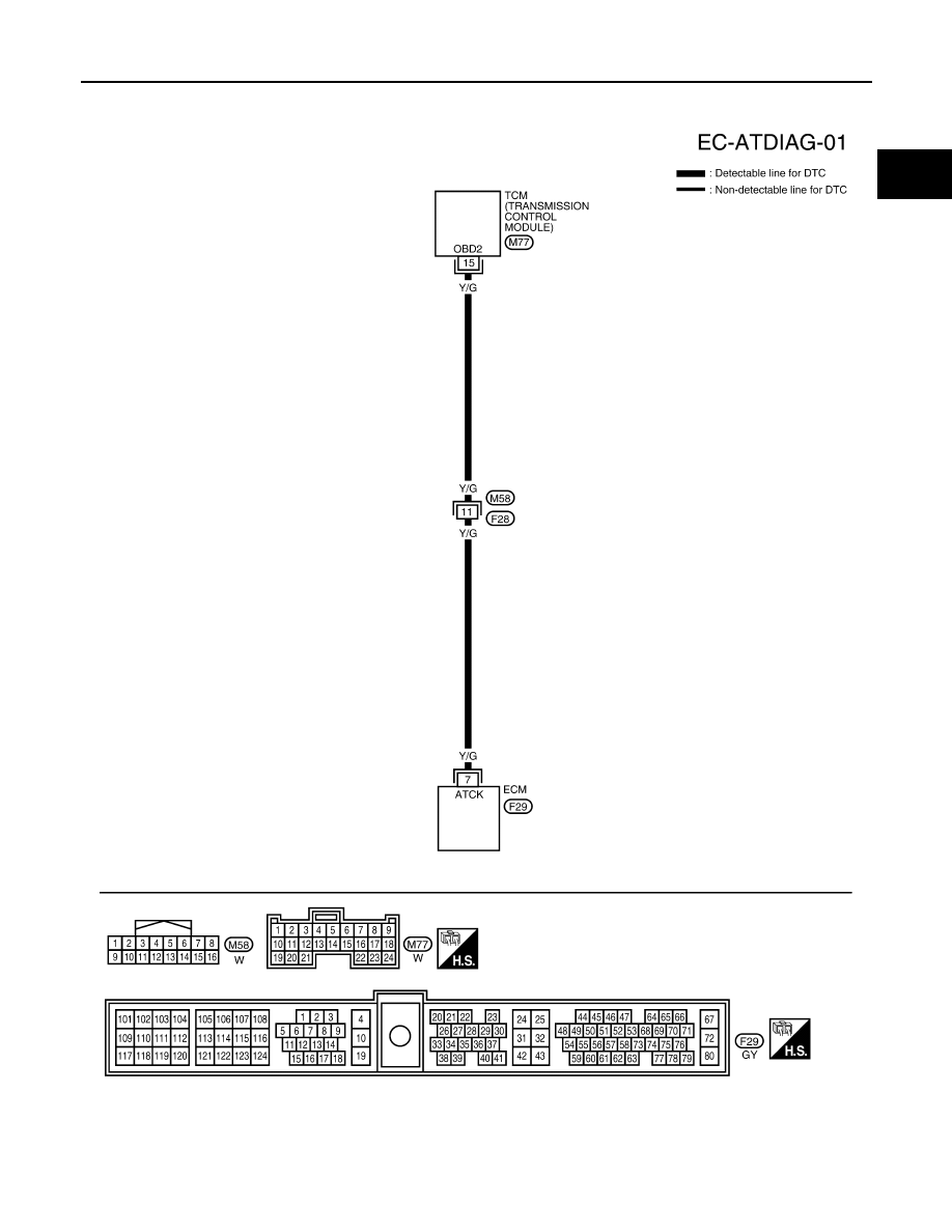
DTC P1605 A/T DIAGNOSIS COMMUNICATION LINE
EC-1123
[VG33E]
C
D
E
F
G
H
I
J
K
L
M
A
EC
Wiring Diagram
UBS00DPV
WITHOUT VDC
BBWA1095E
|
|
|
DTC P1605 A/T DIAGNOSIS COMMUNICATION LINE EC-1123 [VG33E] C D E F G H I J K L M A EC Wiring Diagram UBS00DPV WITHOUT VDC BBWA1095E |