Nissan Frontier D22. Manual - part 504


  Index      Nissan     Nissan Frontier D22 Pickup (1998-2004 year) - Service and Repair Manual


Search            


Content   ..  502  503  504  505   ..


Nissan Frontier D22. Manual - part 504


DTC P1491 VACUUM CUT VALVE BYPASS VALVE

EC-1119

[VG33E]

C

D

E

F

G

H

I

J

K

L

M

A

EC

12. 

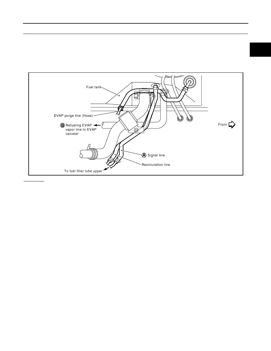
CHECK REFUELING CONTROL VALVE

1.

Remove fuel filler cap.

2.

Check air continuity between hose ends A and B.
Blow air into the hose end B. Air should flow freely into the fuel tank.

3.

Blow air into hose end A and check there is no leakage.

4.

Apply pressure to both hose ends A and B [20 kPa (150 mmHg, 5.91 inHg)] using a pressure pump and a
suitable 3-way connector. Check that there is no leakage.

OK or NG

OK

>> GO TO 13. 

NG

>> Replace fuel tank.

SEF706Z

EC-1120

[VG33E]

DTC P1491 VACUUM CUT VALVE BYPASS VALVE

13. 

CHECK REFUELING EVAP VAPOR CUT VALVE

 With CONSULT-II

1.

Remove fuel tank. Refer to 

FL-3, "FUEL TANK"

 .

2.

Drain fuel from the tank as follows:

Remove fuel feed hose located on the fuel level sensor unit retainer.

Connect a spare fuel hose, one side to fuel level sensor unit retainer where the hose was removed and
the other side to a fuel container.

Drain fuel using “FUEL PUMP RELAY” in “ACTIVE TEST” mode with CONSULT-II.

3.

Check refueling EVAP vapor cut valve for being stuck to close as follows.
Blow air into the refueling EVAP vapor cut valve (from hose end B), and check that the air flows freely into
the tank.

4.

Check EVAP vapor cut valve for being stuck to open as follows.

Connect vacuum pump to hose ends A and B using a suitable 3-way connector.

Remove fuel level sensor unit retainer with fuel level sensor unit.
Always replace O-ring with new one.

Put fuel tank upside down.

Apply vacuum pressure to both hose ends A and B [

−13.3 kPa (−100 mmHg, −3.94 inHg)] with fuel level

sensor unit retainer remaining open and check that the pressure is applicable.

 Without CONSULT-II

1.

Remove fuel tank. Refer to 

FL-3, "FUEL TANK"

 .

2.

Drain fuel from the tank as follows:

Remove fuel level sensor unit retainer.

Drain fuel from the tank using a hand pump into a fuel container.

3.

Check refueling EVAP vapor cut valve for being stuck to close as follows.
Blow air into the refueling EVAP vapor cut valve (from hose end B), and check that the air flows freely into
the tank.

4.

Check EVAP vapor cut valve for being stuck to open as follows.

Connect vacuum pump to hose ends A and B using a suitable 3-way connector.

Remove fuel level sensor unit retainer with fuel level sensor unit.
Always replace O-ring with new one.

Put fuel tank upside down.

Apply vacuum pressure to both hose ends A and B [

−13.3 kPa (−100 mmHg, −3.94 inHg)] with fuel level

SEF707Z

DTC P1491 VACUUM CUT VALVE BYPASS VALVE

EC-1121

[VG33E]

C

D

E

F

G

H

I

J

K

L

M

A

EC

sensor unit retainer remaining open and check that the pressure is applicable.

OK or NG

OK

>> GO TO 14. 

NG

>> Replace fuel tank.

14. 

CHECK INTERMITTENT INCIDENT

Refer to 

EC-696, "TROUBLE DIAGNOSIS FOR INTERMITTENT INCIDENT"

 .

>> INSPECTION END.

SEF707Z

EC-1122

[VG33E]

DTC P1605 A/T DIAGNOSIS COMMUNICATION LINE

DTC P1605 A/T DIAGNOSIS COMMUNICATION LINE

PFP:23710

Component Description

UBS00DPS

The malfunction information related to A/T (Automatic Transmission) is transferred through the line (circuit)
from TCM (Transmission control module) to ECM. Therefore, be sure to erase the malfunction information
such as DTC not only in TCM (Transmission control module) but also ECM after the A/T related repair.

On Board Diagnosis Logic

UBS00DPT

DTC Confirmation Procedure

UBS00DPU

NOTE:
If DTC Confirmation Procedure has been previously conducted, always turn ignition switch OFF and wait at
least 5 seconds before conducting the next test.
TESTING CONDITION:
Before performing the following procedure, confirm that battery voltage is more than 10.5V at idle.

 WITH CONSULT-II

1.

Turn ignition switch ON.

2.

Select “DATA MONITOR” mode with CONSULT-II.

3.

Start engine and wait at least 70 seconds.

4.

If 1st trip DTC is detected, go to 

EC-1126, "Diagnostic Proce-

dure"

 .

 WITH GST

Follow the procedure “WITH CONSULT-II”.

DTC No.

Trouble diagnosis name

DTC detecting condition

Possible cause

P1605

A/T diagnosis communi-
cation line

An incorrect signal from TCM (Transmis-
sion Control Module) is sent to ECM.

Harness or connectors
[The communication line circuit between ECM 
and TCM (Transmission Control Module) is 
open or shorted.]

Dead (Weak) battery

TCM (Transmission Control Module)

SEF985Y


Content   ..  502  503  504  505   ..