Nissan Frontier D22. Manual - part 502


  Index      Nissan     Nissan Frontier D22 Pickup (1998-2004 year) - Service and Repair Manual


Search            


Content   ..  500  501  502  503   ..


Nissan Frontier D22. Manual - part 502


DTC P1491 VACUUM CUT VALVE BYPASS VALVE

EC-1111

[VG33E]

C

D

E

F

G

H

I

J

K

L

M

A

EC

On Board Diagnosis Logic

UBS00DPN

DTC Confirmation Procedure

UBS00DPO

CAUTION:

Always drive vehicle at a safe speed.
NOTE:
If DTC Confirmation Procedure has been previously conducted, always turn ignition switch OFF and wait at
least 5 seconds before conducting the next test.
TESTING CONDITION:
Always perform test at a temperature of 5 to 30

°C (41 to 86°F).

 WITH CONSULT-II

1.

Turn ignition switch ON.

2.

Start engine and warm it up to normal operating temperature.

3.

Turn ignition switch OFF and wait at least 5 seconds. 

4.

Start engine and let it idle for at least 70 seconds.

5.

Select  “VC CUT/V BP/V P1491” of “EVAPORATIVE SYSTEM” in “DTC WORK SUPPORT” mode with
CONSULT-II.

6.

Touch “START”.

7.

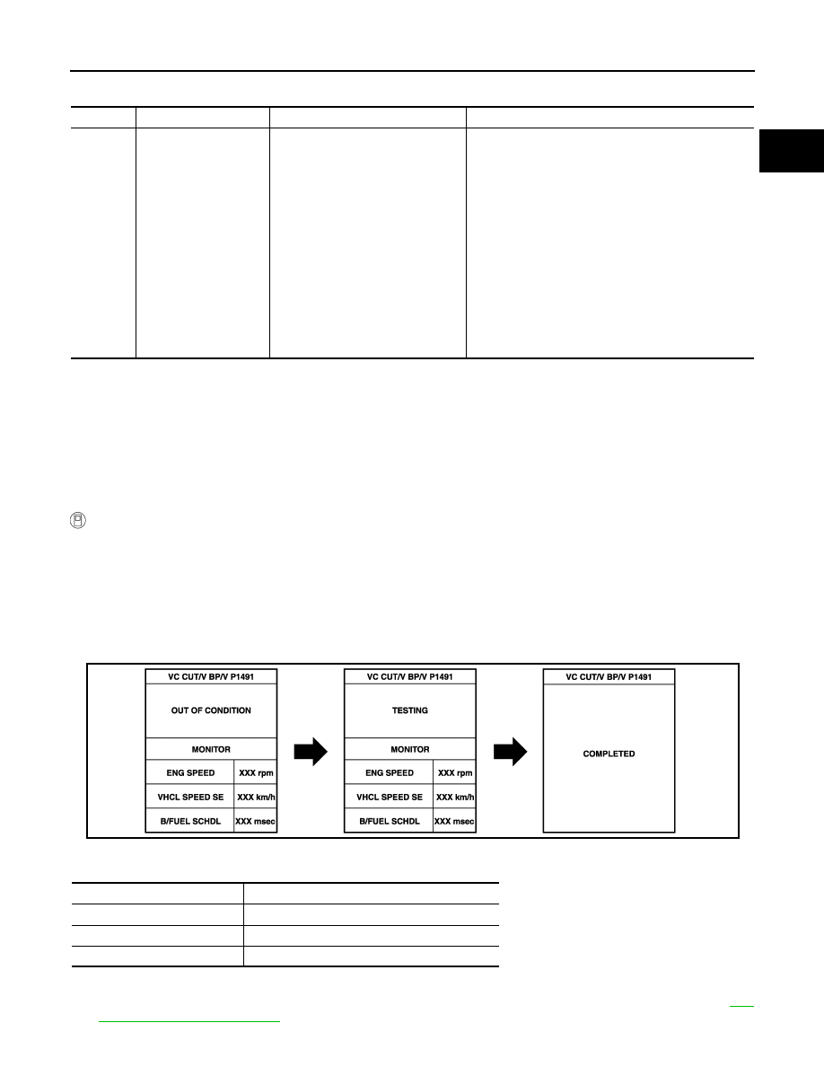
When the following conditions are met, “TESTING” will be displayed on the CONSULT-II screen. Maintain
the conditions continuously until “TESTING” changes to “COMPLETED”. (It will take at least 30 seconds.)

If “TESTING” is not displayed after 5 minutes, retry from step 3.

8.

Make sure that “OK” is displayed after touching “SELF-DIAG RESULTS”. If “NG” is displayed, refer to 

EC-

1114, "Diagnostic Procedure"

 .

DTC No.

Trouble diagnosis name

DTC detecting condition

Possible cause

P1491

Vacuum cut valve 
bypass valve

Vacuum cut valve bypass valve does 
not operate properly.

Vacuum cut valve bypass valve

Vacuum cut valve

Bypass hoses for clogging

EVAP control system pressure sensor and circuit

EVAP canister vent control valve

Hose between fuel tank and vacuum cut valve 
clogged

Hose between vacuum cut valve and EVAP canister 
clogged

EVAP canister

EVAP purge port of fuel tank for clogging

Refueling control valve

Refueling EVAP vapor cut valve

CMPS·RPM (POS)

More than 500 rpm

Selector lever

Suitable position

Vehicle speed

More than 36 km/h (22 MPH)

B/FUEL SCHDL

1.0 - 10.0 msec

PBIB1462E

EC-1112

[VG33E]

DTC P1491 VACUUM CUT VALVE BYPASS VALVE

Overall Function Check

UBS00DPP

Use this procedure to check the overall function of vacuum cut valve bypass valve. During this check, the 1st
trip DTC might not be confirmed.

 WITH GST

1.

Remove vacuum cut valve and vacuum cut valve bypass valve
as an assembly.

2.

Apply vacuum to port A  and check that there is no suction from
port B .

3.

Apply vacuum to port B  and check that there is suction from
port A .

4.

Blow air in port B  and check that there is a resistance to flow out
of port A .

5.

Supply battery voltage to the terminal.

6.

Blow air in port A  and check that air flows freely out of port B .

7.

Blow air in port B  and check that air flows freely out of port A .

8.

If NG, go to 

EC-1114, "Diagnostic Procedure"

 .

SEF530Q

DTC P1491 VACUUM CUT VALVE BYPASS VALVE

EC-1113

[VG33E]

C

D

E

F

G

H

I

J

K

L

M

A

EC

Wiring Diagram

UBS00DPQ

BBWA1094E

EC-1114

[VG33E]

DTC P1491 VACUUM CUT VALVE BYPASS VALVE

Specification data are reference values and are measured between each terminal and ground.

CAUTION:

Do not use ECM ground terminals when measuring input/output voltage. Doing so may result in dam-
age to the ECM's transistor. Use a ground other than the ECM terminals, such as the ground.

Diagnostic Procedure

UBS00DPR

1. 

INSPECTION START

Do you have CONSULT-II?
Yes or No

Yes

>> GO TO 2.

No

>> GO TO 3.

2. 

CHECK VACUUM CUT VALVE BYPASS VALVE OPERATION

 With CONSULT-II

1.

Turn ignition switch OFF.

2.

Remove vacuum cut valve and vacuum cut valve bypass valve as an assembly.

3.

Apply vacuum to port A and check that there is no suction from port B.

4.

Apply vacuum to port B and check that there is suction from port A.

5.

Blow air in port B and check that there is a resistance to flow out of port A.

6.

Turn ignition switch ON.

7.

Select “VC/V BYPASS/V” in “ACTIVE TEST” mode with CONSULT-II and touch “ON”.

8.

Blow air in port A and check that air flows freely out of port B.

9.

Blow air in port B and check that air flows freely out of port A.

OK or NG

OK

>> GO TO 4.

NG

>> GO TO 5.

 TER-

MINAL 

NO.

WIRE 

COLOR

ITEM

CONDITION

DATA (DC Voltage)

120

P/B

Vacuum cut valve bypass 
valve

[Ignition switch: ON] 

BATTERY VOLTAGE
(11 - 14V)

SEF017Z


Content   ..  500  501  502  503   ..