Nissan Frontier D22. Manual - part 506


  Index      Nissan     Nissan Frontier D22 Pickup (1998-2004 year) - Service and Repair Manual


Search            


Content   ..  504  505  506  507   ..


Nissan Frontier D22. Manual - part 506


DTC P1706 PNP SWITCH

EC-1127

[VG33E]

C

D

E

F

G

H

I

J

K

L

M

A

EC

DTC P1706 PNP SWITCH

PFP:32006

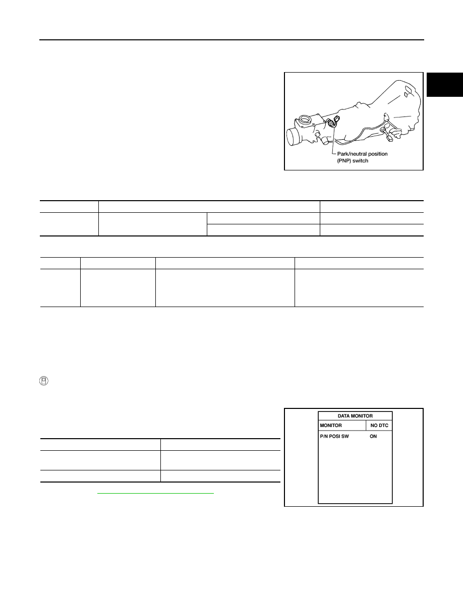
Component Description

UBS00DPX

When the gear position is P or N (A/T), Neutral (M/T), park/neutral
position (PNP) switch is ON.
ECM detects the position because the continuity of the line (the ON
signal) exists.
For A/T models, the park/neutral position (PNP) switch assembly
also includes a transmission range switch to detect selector lever
position.

CONSULT-II Reference Value in Data Monitor Mode

UBS00DPY

Specification data are reference values.

On Board Diagnosis Logic

UBS00DPZ

DTC Confirmation Procedure

UBS00DQ0

CAUTION:

Always drive vehicle at a safe speed.

NOTE:
If DTC Confirmation Procedure has been previously conducted, always turn ignition switch OFF and wait at
least 5 seconds before conducting the next test.

 WITH CONSULT-II

1.

Turn ignition switch ON.

2.

Select  “P/N POSI SW” in “DATA MONITOR” mode with CON-
SULT-II. Then check the “P/N POSI SW” signal under the follow-
ing conditions.

If NG, go to 

EC-1130, "Diagnostic Procedure"

 .

If OK, go to following step.

3.

Select “DATA MONITOR” mode with CONSULT-II.

4.

Start engine and warm it up to normal operating temperature.

AEC877A

MONITOR ITEM

CONDITION

SPECIFICATION

P/N POSI SW

Ignition switch: ON

Shift lever: P or N (A/T), Neutral (M/T)

ON

Except above

OFF

DTC No.

Trouble diagnosis name

DTC detecting condition

Possible cause

P1706

Park/neutral position 
switch

The signal of the park/neutral position (PNP) 
switch is not changed in the process of engine 
starting and driving.

Harness or connectors
[The park/neutral position (PNP) switch 
circuit is open or shorted.]

Park/neutral position (PNP) switch

Position (Selector lever)

 Known good signal

N or P position (A/T)
Neutral position (M/T)

ON

Except above position

OFF

SEF212Y

EC-1128

[VG33E]

DTC P1706 PNP SWITCH

5.

Maintain the following conditions for at least 60 consecutive sec-
onds.

6.

If 1st trip DTC is detected, go to 

EC-1130, "Diagnostic Proce-

dure"

 .

Overall Function Check

UBS00DQ1

Use this procedure to check the overall function of the park/neutral position (PNP) switch circuit. During this
check, a 1st trip DTC might not be confirmed.

 WITH GST

1.

Turn ignition switch ON.

2.

Check voltage between ECM terminal 22 and body ground
under the following conditions.

3.

If NG, go to 

EC-1130, "Diagnostic Procedure"

 .

ENG SPEED

1,600 - 2,700 rpm

COOLAN TEMP/S

More than 70

°C (158°F)

B/FUEL SCHDL

3.3 - 13.0 msec

VHCL SPEED SE

More than 64 km/h (40 MPH)

Selector lever

Suitable position

SEF213Y

Condition (Gear position)

Voltage (V) (Known-good data)

P or N position (A/T)
Neutral position (M/T)

Approx. 0

Except above position

Approx. 5

SEF877U

DTC P1706 PNP SWITCH

EC-1129

[VG33E]

C

D

E

F

G

H

I

J

K

L

M

A

EC

Wiring Diagram

UBS00DQ2

BBWA1096E

EC-1130

[VG33E]

DTC P1706 PNP SWITCH

Specification data are reference values and are measured between each terminal and ground.

CAUTION:

Do not use ECM ground terminals when measuring input/output voltage. Doing so may result in dam-
age to the ECM's transistor. Use a ground other than the ECM terminals, such as the ground.

Diagnostic Procedure

UBS00DQ3

FOR M/T MODELS

1. 

CHECK PNP SWITCH GROUND CIRCUIT FOR OPEN AND SHORT

1.

Turn ignition switch OFF.

2.

Disconnect park/neutral position (PNP) switch harness connec-
tor.

3.

Check harness continuity between PNP switch terminal 2 and
engine ground. Refer to Wiring Diagram.

4.

Also check harness for short to power.

OK or NG

OK

>> GO TO 3.

NG

>> GO TO 2.

2. 

DETECT MALFUNCTIONING PART

Check the following.

Harness connectors F201, F43

Harness for open between park/neutral position (PNP) switch and engine ground

>> Repair open circuit or short to power in harness or connectors.

3. 

CHECK PNP SWITCH INPUT SIGNAL CIRCUIT FOR OPEN AND SHORT

1.

Disconnect ECM harness connector.

2.

Check harness continuity between ECM terminal 22 and PNP switch terminal 1. Refer to Wiring Diagram.

3.

Also check harness for short to ground and short to power.

OK or NG

OK

>> GO TO 5.

NG

>> GO TO 4.

4. 

DETECT MALFUNCTIONING PART

Check the following.

Harness connectors F43, F201

Harness for open or short between ECM and park/neutral position (PNP) switch

>> Repair open circuit or short to ground or short to power in harness or connectors.

TER-

MINAL 

NO.

WIRE 

COLOR

ITEM

CONDITION

DATA (DC Voltage)

22

L/B

Park/neutral position 
(PNP) switch

[Ignition switch: ON] 

Shift lever: N or P (A/T), Neutral (M/T)

Approximately 0V

[Ignition switch: ON]

Except above position

Approximately 5V

Continuity should exist.

AEC877A

Continuity should exist.


Content   ..  504  505  506  507   ..