Nissan Xterra. Manual - part 682


  Index      Nissan     Nissan Xterra (2014 year) - Service and Repair Manual


Search            


Content   ..  680  681  682  683   ..


Nissan Xterra. Manual - part 682


CONTROL VALVE WITH TCM

TM-241

< REMOVAL AND INSTALLATION >

[5AT: RE5R05A]

C

E

F

G

H

I

J

K

L

M

A

B

TM

N

O

P

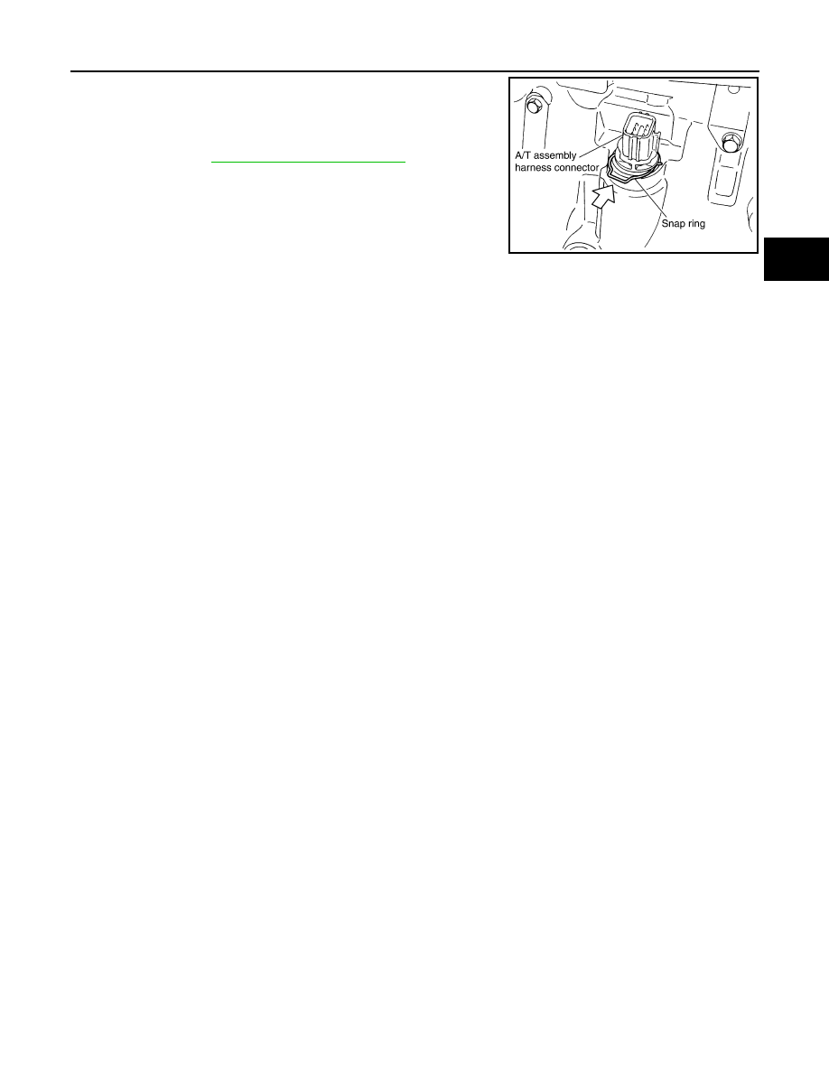
15. Install snap ring to A/T assembly harness connector.
16. Connect A/T assembly harness connector.
17. Connect the negative battery terminal.
18. Refill the A/T with fluid and check the fluid level and for fluid

leakage. Refer to 

MA-12, "Fluids and Lubricants"

.

SCIA5039E

TM-242

< REMOVAL AND INSTALLATION >

[5AT: RE5R05A]

REAR OIL SEAL

REAR OIL SEAL

Removal and Installation

INFOID:0000000009485607

NOTE:

When removing components such as hoses, tubes/lines, etc., cap or plug openings to prevent fluid from spill-

ing.

REMOVAL

1. Remove rear propeller shaft. Refer to 

DLN-140, "Removal and Installation"

 (2S1330) or 

DLN-149,

"Removal and Installation"

 (2S1330-BJ100).

2. Remove transfer from transmission (4WD models). Refer to 

DLN-99, "Removal and Installation"

 (TX15B).

3. Remove rear oil seal using flat bladed screwdriver.

CAUTION:

Do not scratch rear extension assembly (2WD models) or

adapter case assembly (4WD models).

INSTALLATION

SCIA5254E

REAR OIL SEAL

TM-243

< REMOVAL AND INSTALLATION >

[5AT: RE5R05A]

C

E

F

G

H

I

J

K

L

M

A

B

TM

N

O

P

1. Install new rear oil seal until it is flush into the rear extension

case (2WD models) using Tool or adapter case (4WD models)

using suitable tool.

CAUTION:

• Apply ATF to rear oil seal.

• Do not reuse rear oil seal.

2. Install transfer to transmission (4WD models). Refer to 

DLN-99,

"Removal and Installation"

 (TX15B).

3. Install rear propeller shaft. Refer to 

DLN-140, "Removal and

Installation"

 (2S1330) or 

DLN-149, "Removal and Installation"

(2S1330-BJ100)

4. Check the A/T fluid level and for fluid leaks. Refer to 

TM-215,

"Checking the A/T Fluid (ATF)"

.

Tool number

: ST33400001 (J-26082)

WCIA0475E

TM-244

< REMOVAL AND INSTALLATION >

[5AT: RE5R05A]

KEY INTERLOCK CABLE

KEY INTERLOCK CABLE

Component

INFOID:0000000009485608

CAUTION:

• Install key interlock cable in such a way that it will not be damaged by sharp bends, twists or interfer-

ence with adjacent parts.

• After installing key interlock cable to shift selector, make sure that casing cap and bracket are firmly

secured in their positions. If casing cap can be removed with an external load of less than 39 N (4.0

kg, 8.8 lb), replace key interlock cable with new one.

Removal and Installation

INFOID:0000000009485609

REMOVAL

1. Remove the center console. Refer to 

IP-24, "Exploded View"

2. Remove instrument lower panel LH. Refer to 

IP-10, "Exploded View"

.

WCIA0467E


Content   ..  680  681  682  683   ..