Nissan Xterra. Manual - part 489
IP-24
< UNIT DISASSEMBLY AND ASSEMBLY >
CENTER CONSOLE ASSEMBLY
CENTER CONSOLE ASSEMBLY
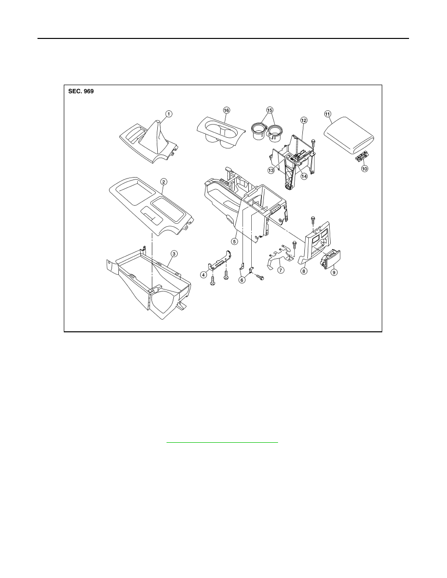
Exploded View
INFOID:0000000009485686
Disassembly and Assembly
INFOID:0000000009485687
DISASSEMBLY
1. Remove center console. Refer to
IP-21, "Removal and Installation"
2. Remove center console lid.
3. Remove hinge from center console lid.
4. Remove rear finisher assembly.
5. Remove rear cup holder assembly.
6. Remove brackets.
7. Disconnect the harness connectors from center console.
8. Remove cup holder insert and cup holder finisher.
9. Remove center console bin.
10. Remove center console bracket.
11. Remove wire harness bracket.
AWJIA1014ZZ
1.
Shift selector finisher (M/T)
2.
Shift selector finisher (A/T)
3.
Center console front base
4.
Bracket
5.
Center console rear base
6.
Bracket
7.
Wire harness bracket
8.
Rear finisher assembly
9.
Rear cup holder assembly
10. Center console lid hinge
11. Center console lid
12. Center console bin
13. USB connector
14. Power Socket
15. Cup holder insert
16. Cup holder finisher
A.
Bolt