Nissan Xterra. Manual - part 431


  Index      Nissan     Nissan Xterra (2014 year) - Service and Repair Manual


Search            


Content   ..  429  430  431  432   ..


Nissan Xterra. Manual - part 431


FAX-14

< UNIT DISASSEMBLY AND ASSEMBLY >

DRIVE SHAFT

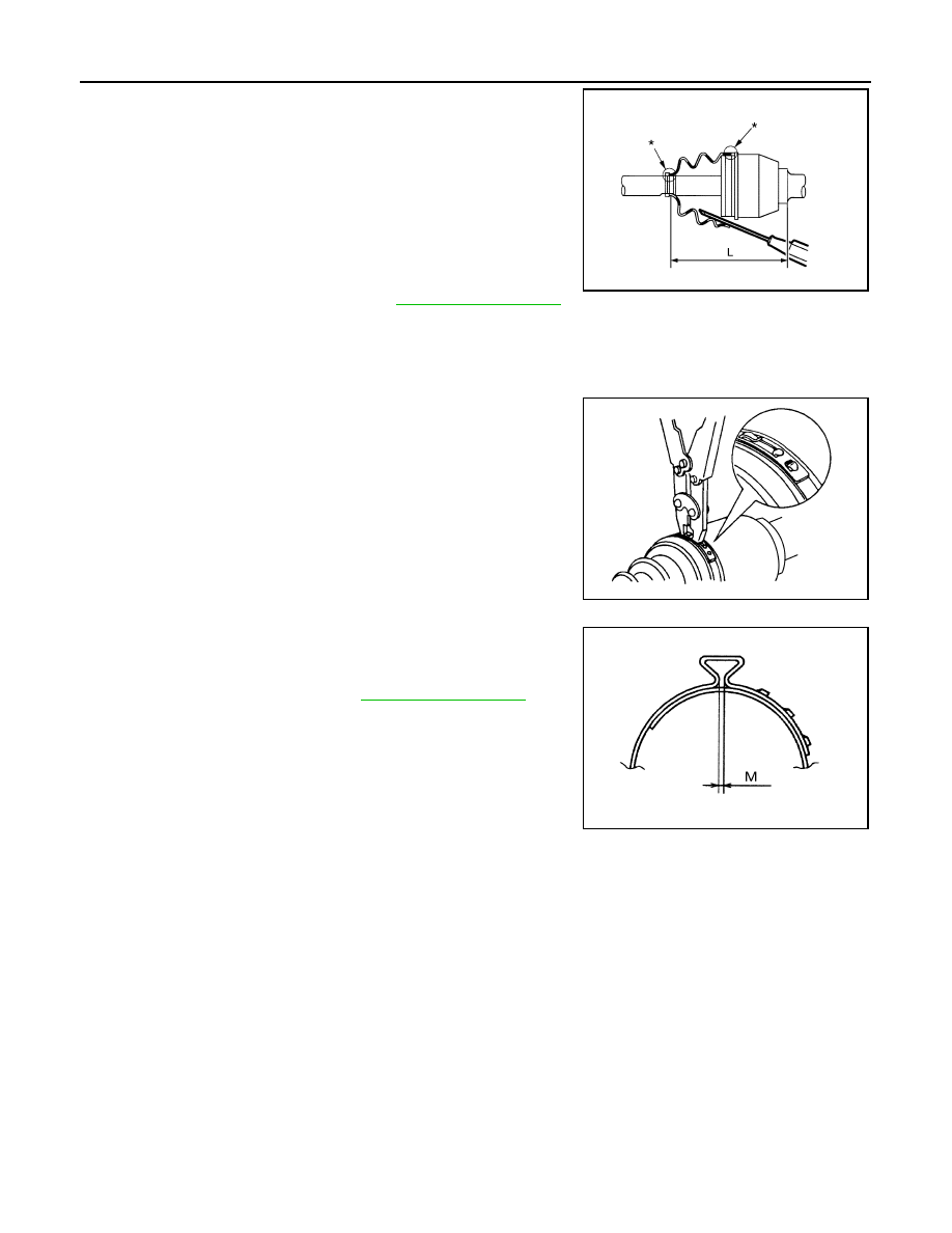
6. Install the boot securely into the grooves (indicated by the *

marks) as shown.

CAUTION:

If there is grease on the boot mounting surfaces (indicated

by the * marks) of the shaft and joint sub-assembly, the

boot may come off. Remove all grease from the drive shaft

surfaces. 

7. Check that the boot installation length (L) is the specified length.

Insert a suitable tool into the large end of the boot. Bleed the air

from the boot to prevent boot deformation. 

CAUTION:

• The boot may break if the boot installation length is less than the specified length.

• Do not contact inside surface of boot with the tip of the suitable tool.

8. Secure large and small ends of the boot using new boot bands

using tool as shown.

CAUTION:

Do not reuse boot bands.

• Secure boot band so that dimension (M) meets specification

as shown.

9. After installing the housing to the shaft, rotate the boot to check

that it is positioned correctly. If the boot is not positioned cor-

rectly, remove the old boot bands then reposition the boot and

secure the boot with new boot bands.

Boot installation 

length (L)

: Refer to 

FAX-15, "Drive Shaft"

.

Tool number : KV40107300 ( — )

JPDIF0142ZZ

RAC1133D

Dimension (M)

: Refer to 

FAX-15, "Drive Shaft"

.

DSF0047D

SERVICE DATA AND SPECIFICATIONS (SDS)

FAX-15

< SERVICE DATA AND SPECIFICATIONS (SDS) 

C

E

F

G

H

I

J

K

L

M

A

B

FAX

N

O

P

SERVICE DATA AND SPECIFICATIONS (SDS)

SERVICE DATA AND SPECIFICATIONS (SDS)

Wheel Bearing

INFOID:0000000009484367

Drive Shaft

INFOID:0000000009484368

Boot Bands

INFOID:0000000009484369

Unit: mm (in)

Axial end play limit

0.05 mm (0.002 in) or less

Drive shaft joint type

Final drive side

Rzeppa

Wheel side

Rzeppa

Grease

Specification

Genuine NISSAN Grease or equivalent

Capacity

Final drive side

120 - 140 g (4.23 - 4.94 oz)

Wheel side

110 - 130 g (3.88 - 4.59 oz)

Boot installed length (L)

Final drive side

163.9 - 164.3 mm (6.45 - 6.47 in)

Wheel side

135.1 mm (5.32 in)

AWDIA0682GB

Dimension (M)

1.0 - 4.0 (0.039 - 0.157)

DSF0047D

FL-1

ENGINE

C

D

E

F

G

H

I

J

K

L

M

SECTION 

FL

A

FL

N

O

P

CONTENTS

FUEL SYSTEM

PRECAUTION ...............................................

2

PRECAUTIONS ...................................................

2

Precaution for Supplemental Restraint System 
(SRS) "AIR BAG" and "SEAT BELT PRE-TEN-
SIONER" .................................................................
..

2

General Precaution  ...................................................

2

PREPARATION ............................................

4

PREPARATION ...................................................

4

Special Service Tool  .................................................

4

Commercial Service Tool  ..........................................

4

PERIODIC MAINTENANCE ..........................

5

FUEL SYSTEM ....................................................

5

Checking Fuel Line  ...................................................

5

REMOVAL AND INSTALLATION ................

6

FUEL TANK .........................................................

6

Removal and Installation ...........................................

6

FUEL LEVEL SENSOR UNIT, FUEL FILTER 
AND FUEL PUMP ASSEMBLY  ........................

11

Removal and Installation  .........................................

11

EVAP CANISTER ..............................................

16

Component Inspection .............................................

16

Removal and Installation  .........................................

16

UNIT DISASSEMBLY AND ASSEMBLY  ....

18

FUEL LEVEL SENSOR UNIT, FUEL FILTER 
AND FUEL PUMP ASSEMBLY  ........................

18

Disassembly and Assembly .....................................

18

SERVICE DATA AND SPECIFICATIONS 
(SDS) ............................................................

19

SERVICE DATA AND SPECIFICATIONS 
(SDS) .................................................................

19

Standard and Limit  ..................................................

19

FL-2

< PRECAUTION >

PRECAUTIONS

PRECAUTION

PRECAUTIONS

Precaution for Supplemental Restraint System (SRS) "AIR BAG" and "SEAT BELT 
PRE-TENSIONER"

INFOID:0000000010202387

The Supplemental Restraint System such as “AIR BAG” and “SEAT BELT PRE-TENSIONER”, used along

with a front seat belt, helps to reduce the risk or severity of injury to the driver and front passenger for certain

types of collision. This system includes seat belt switch inputs and dual stage front air bag modules. The SRS

system uses the seat belt switches to determine the front air bag deployment, and may only deploy one front

air bag, depending on the severity of a collision and whether the front occupants are belted or unbelted.

Information necessary to service the system safely is included in the SR and SB section of this Service Man-

ual.

WARNING:

• To avoid rendering the SRS inoperative, which could increase the risk of personal injury or death in

the event of a collision which would result in air bag inflation, all maintenance must be performed by

an authorized NISSAN/INFINITI dealer.

• Improper maintenance, including incorrect removal and installation of the SRS, can lead to personal

injury caused by unintentional activation of the system. For removal of Spiral Cable and Air Bag

Module, see the SR section.

• Do not use electrical test equipment on any circuit related to the SRS unless instructed to in this

Service Manual. SRS wiring harnesses can be identified by yellow and/or orange harnesses or har-

ness connectors.

PRECAUTIONS WHEN USING POWER TOOLS (AIR OR ELECTRIC) AND HAMMERS

WARNING:

• When working near the Airbag Diagnosis Sensor Unit or other Airbag System sensors with the Igni-

tion ON or engine running, DO NOT use air or electric power tools or strike near the sensor(s) with a

hammer. Heavy vibration could activate the sensor(s) and deploy the air bag(s), possibly causing

serious injury.

• When using air or electric power tools or hammers, always switch the Ignition OFF, disconnect the

battery and wait at least three minutes before performing any service.

General Precaution

INFOID:0000000009484530

WARNING:

When replacing fuel line parts, be sure to observe the following.

• Put a “CAUTION: FLAMMABLE” sign in the workshop.

• Be sure to work in a well ventilated area and furnish the workshop with a CO

2

 fire extinguisher. 

• Do not smoke while servicing the fuel system. Keep open flames and sparks away from the work

area.

CAUTION:

• Use gasoline required by the regulations for the octane rating number. Refer to 

GI-29, "Fuel"

.

• Before removing fuel line parts, carry out the following procedures:

- Put drained fuel in an explosion-proof container and put the lid on securely. Keep the container in

safe area.

- Release fuel pressure from the fuel lines. Refer to 

EC-494, "Fuel Pressure Check"

.

- Disconnect the battery negative terminal. 

• Always replace O-rings and clamps with new ones.

• Do not kink or twist hoses when they are being installed.

• Do not tighten hose clamps excessively to avoid damaging hoses. 

• Tighten high-pressure rubber hose clamp so that clamp end is 3 mm (0.12 in) from hose end.

• Ensure that clamp screw does not contact adjacent parts.


Content   ..  429  430  431  432   ..