Nissan Xterra. Manual - part 430


  Index      Nissan     Nissan Xterra (2014 year) - Service and Repair Manual


Search            


Content   ..  428  429  430  431   ..


Nissan Xterra. Manual - part 430


FAX-10

< UNIT DISASSEMBLY AND ASSEMBLY >

DRIVE SHAFT

UNIT DISASSEMBLY AND ASSEMBLY

DRIVE SHAFT

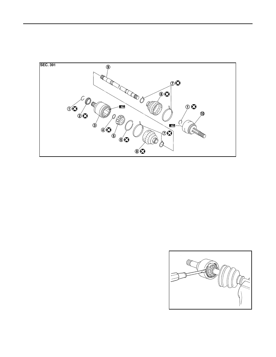
Disassembly and Assembly

INFOID:0000000009484366

DISASSEMBLY

Final Drive Side

1. Mount the drive shaft in a vise.

CAUTION:

When mounting the drive shaft in a vise, use copper or aluminum plates between the vise and the

drive shaft.

2. Remove boot bands and slide the boot back.
3. Put matching marks on housing and shaft before separating joint assembly.

CAUTION:

Use paint or similar substance for matching marks. Do not scratch the surfaces.

4. Remove the stopper ring with a suitable tool as shown, and pull

the housing off.

1.

Circlip

2.

Dust cover

3.

Housing

4.

Snap ring

5.

Ball cage, steel ball and inner race assembly

6.

Stopper ring

7.

Boot band

8.

Boot

9.

Shaft

10.

Joint sub-assembly

WDIA0342E

SFA476

DRIVE SHAFT

FAX-11

< UNIT DISASSEMBLY AND ASSEMBLY >

C

E

F

G

H

I

J

K

L

M

A

B

FAX

N

O

P

5. Remove the snap ring, then remove the ball cage, steel ball,

inner race assembly from the shaft.

6. Remove the boot from the shaft.
7. Remove circlip and dust cover from housing.
8. Clean the old grease off of the housing using paper towels.

Wheel Side

1. Mount the drive shaft in a vise.

CAUTION:

When mounting the drive shaft in a vise, use copper or aluminum plates between the vise and the

drive shaft.

2. Remove the boot bands and slide the boot back.
3. Screw a sliding hammer or suitable tool 30 mm (1.18 in) or more

into threaded part of joint sub-assembly. Pull joint sub-assembly

off of shaft as shown.

CAUTION:

If the joint sub-assembly cannot be removed after five or

more unsuccessful attempts, replace the entire drive shaft

assembly.

NOTE:

Align the sliding hammer and shaft and remove the joint sub-

assembly by pulling directly.

4. Remove boot from the shaft.
5. Remove circlip from the shaft.
6. While rotating the ball cage, clean the old grease off of the joint sub-assembly using paper towels.

INSPECTION AFTER DISASSEMBLY

Shaft

• Replace the shaft if there is any bending, cracking, or other damage.

Joint Sub-assembly

• Check for any rough rotation or unusual axial looseness.

• Clean any foreign material from inside the joint sub-assembly.

• Check for any compression scars, cracks, or fractures.

CAUTION:

If any irregular conditions are found in the joint sub-assembly components, replace the entire joint

sub-assembly.

Housing

NOTE:

Housing, ball cage, steel ball, and inner race are in a set.

• Check for any compression scars, cracks, fractures, or unusual wear on the ball rolling surface.

• Check for any deformation of the boot installation components.

Ball Cage

• Check the sliding surface for any compression scars, cracks, or fractures of sliding surface.

Steel Ball

• Check for any compression scars, cracks, fractures, or unusual wear.

Inner Race

• Check the ball sliding surface for any compression scars, cracks, or fractures.

• Check for any damage to the serrated part.

ASSEMBLY

SFA514A

SDIA0606E

FAX-12

< UNIT DISASSEMBLY AND ASSEMBLY >

DRIVE SHAFT

Final Drive Side

1. Wrap the serrated part of the shaft with tape. Install the boot

band and boot to shaft.

CAUTION:

Do not reuse boot band and boot.

2. Remove the tape wound around the serrated part of the shaft.

3. Install the ball cage, steel ball, and inner race assembly on the

shaft, and secure them using the snap ring.

CAUTION:

Do not reuse snap ring.

4. Insert the specified quantity of Genuine NISSAN Grease or

equivalent, into the housing. Refer to 

MA-12, "Fluids and Lubri-

cants"

.

CAUTION:

If grease adheres to the boot mounting surface (indicated

by * marks) on shaft and housing, boot may come off.

Remove all grease from surfaces.

5. Install the stopper ring onto the housing.

CAUTION:

• Do not reuse stopper rings.

• Make sure that housing and stopper ring are fully engaged.

6. Install the boot securely into the grooves (indicated by * marks)

as shown.

CAUTION:

If there is grease on boot mounting surfaces (indicated by *

marks) of shaft and housing, boot may come off. Remove

all grease from surfaces.

7. Check that the boot installation length (L) is the length indicated

below. Insert a suitable tool into large side of boot. Bleed air

from boot to prevent boot deformation.

CAUTION:

• The boot may break if the boot installation length is less than the specified value.

• Do not to touch the tip of the suitable tool to the inside of the boot.

SFA800

SDIA1125E

Grease capacity

: Refer to 

FAX-15, "Drive 

Shaft"

.

SDIA1446E

Boot installation 

length (L)

: Refer to 

FAX-15, "Drive 

Shaft"

.

AWDIA0681GB

DRIVE SHAFT

FAX-13

< UNIT DISASSEMBLY AND ASSEMBLY >

C

E

F

G

H

I

J

K

L

M

A

B

FAX

N

O

P

8. Secure the big and small ends of the boot with the new boot

bands as shown. 

CAUTION:

Do not reuse boot bands.

9. Secure housing and shaft and then make sure that they are in the correct position when rotating boot. Use

a new boot band if the boot band needs to be loosened to reposition the boot.

10. Install circlip and dust cover to housing.

CAUTION:

Do not reuse circlip and dust cover.

Wheel Side

1. Insert the Genuine NISSAN Grease or equivalent, into the joint

sub-assembly serration hole until the grease begins to ooze

from the ball groove and serration hole. Refer to 

MA-12, "Fluids

and Lubricants"

. After inserting the grease, use a shop cloth to

wipe off the grease that has oozed out.

2. Wrap the serrated part of the shaft with tape. Install the boot

band and boot onto the shaft. Do not damage the boot.

CAUTION:

Do not reuse boot band and boot.

3. Remove the protective tape wound around the serrated part of

the shaft.

4. Attach the circlip to the shaft. The circlip must fit securely into

the shaft groove. Attach the nut to the joint sub-assembly.

Use a soft hammer to press-fit the circlip.

CAUTION:

Do not reuse circlip.

5. Insert the specified quantity of Genuine NISSAN Grease or equivalent, into the joint sub-assembly and

the large end of the boot. Refer to 

MA-12, "Fluids and Lubricants"

.

SFA395

SDIA1127E

SFA800

RAC0049D

Grease capacity

: Refer to 

FAX-15, "Drive Shaft"

.


Content   ..  428  429  430  431   ..