Nissan Xterra. Manual - part 429
FAX-6
< UNIT REMOVAL AND INSTALLATION >
DRIVE SHAFT
UNIT REMOVAL AND INSTALLATION
DRIVE SHAFT
Removal and Installation
INFOID:0000000009484364
REMOVAL
1. Remove wheel and tire using power tool. Refer to
2. Remove the engine under cover using power tool. Refer to
EXT-15, "Removal and Installation"
.
3. Remove wheel sensor harness from mount on knuckle, then disconnect wheel sensor harness connector.
CAUTION:
Do not pull on wheel sensor harness.
4. Remove wheel hub and bearing assembly. Refer to
FAX-8, "Removal and Installation"
.
• It is not necessary to remove wheel sensor from wheel hub when wheel hub is not being replaced.
• Carefully feed wheel sensor harness through hole in splash shield.
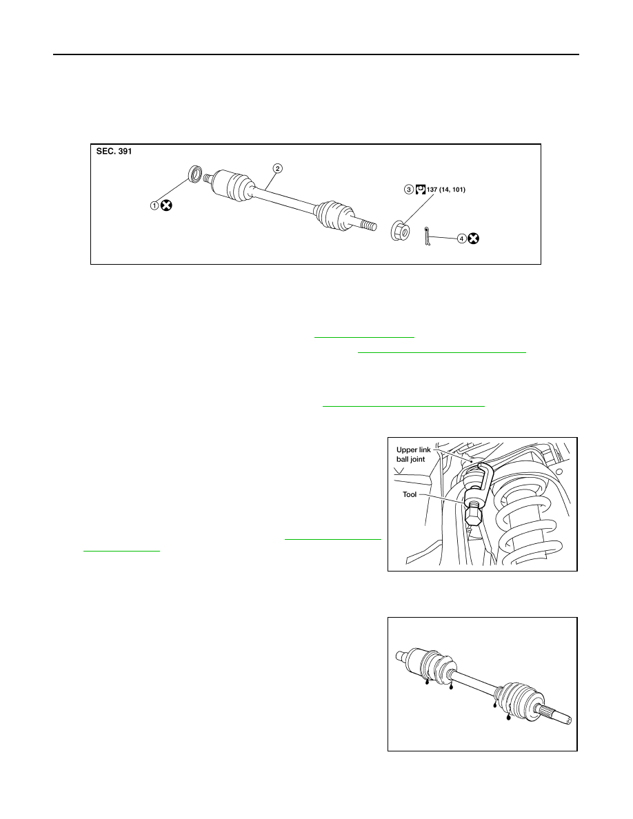
5. Separate upper link ball joint stud from steering knuckle using
Tool.
• Support lower link with jack.
6. Remove drive shaft assembly.
• Pry drive shaft from front final drive using suitable tool.
• Remove differential side oil seal. Refer to
INSPECTION AFTER REMOVAL
• Move joint up, down, left, right, and in axial direction. Check for any rough movement or significant loose-
ness.
• Check boot for cracks or other damage, and for grease leakage.
• If damaged, disassemble drive shaft to verify damage, and repair
or replace as necessary.
INSTALLATION
Installation is in the reverse order of removal.
1.
Differential side oil seal
2.
Drive shaft
3.
Drive shaft lock nut
4.
Cotter pin
WDIA0341E
Tool number
: ST29020001 (J-24319-B)
WEIA0119E
SFA108A